


11
Chapter 2
Getting Started
Introduction
This chapter will help you get off to a good start with your ST-133 Controller. In addition
to descriptions of such basics as unpacking and grounding safety, the chapter includes
discussions of the requirements that have to be met before the camera can be switched on.
Included are environmental, power, computer, and software requirements. Also provided
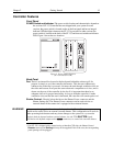
are descriptions of the front and rear panels of the components, together with discussions
of mounting, imaging and other topics. Users are advised to read this chapter in its
entirety before powering up the system.
Unpacking
During unpacking, check the controller for possible signs of shipping damage. If there are
any, notify Roper Scientific and file a claim with the carrier. If damage is not apparent
but controller specifications cannot be achieved, internal damage may have occurred in
shipment.
Equipment and Parts Inventory
The complete system consists of a camera, a controller and other components as follows:
• Camera to Controller cable: DB25 to DB25 cable. Standard length is 10 ft
(6050-0321 for TE-cooled cameras; 6050-0361 for LN-cooled). Also available in 6’,
15’, 20’, and 30’ lengths.
• Controller to Computer Interface (TAXI or USB 2.0):
Note: For convenience, in the following operating-procedure discussions, this
manual refers to a Pentium™ PC equipped with a PCI high-speed interface card and
using WinView/32 software. Nevertheless, the manual does apply as well to
operation with other computers and software. Interface components, as follows,
could be required.
• TAXI interface
High Speed PCI Interface board: High-speed serial interface card installed in
the host computer.
TAXI Interface Control Module: Interface module installed in the ST-133.
Cable: DB9 to DB9 cable. Standard length is 25 ft (6050-0148-CE). Lengths
up to 165 ft (50 m) are available.