


22 ST-133 Controller Manual Version 3.B
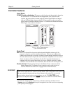
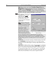
F and S Zero adjustments: These 10-turn potentiometers control the offset
values of the Fast (F) and Slow (S) A/D converters. The offset is a voltage
that is added to the signal to bring the A/D output to a non-zero value,
typically 50-100 counts. This offset value ensures that all the true variation
in the signal can really be seen and not lost below the A/D "0" value. Since
the offset is added to the signal, these counts only minimally reduce the
range of the signal to a value in the range of 50-100 counts lower.
Adjusting a potentiometer clockwise increases the counts while rotating it
counterclockwise decreases the counts. For controllers with only one A/D
converter (F), the second pot (S) will not be activated.
Note that the offset is preadjusted for optimum system performance at
the factory and should not normally need adjusting. However, to
accommodate the widest possible range of measurement conditions,
these adjustments are made user accessible.
If these potentiometers are not present, offset may be software-adjustable.
Do not adjust the offset values to zero, or some low-level data will be missed.
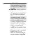
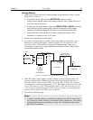
Detector connector: A cable
*
that interconnects the Controller and the Camera
connects to this 25-pin connector (type DB25). This connector, the cable,
and the corresponding connector on the camera are configured so that the
cable cannot be installed incorrectly. Note that this cable is secured by a
slide-lock mechanism at the end that connects to the controller. The other
end will be secured by screws or by a slide-lock as required by the camera.
To ensure reliable operation, it is essential that both ends of the cable
connector be secured before powering the controller.
Always turn the power off at the Controller before connecting or disconnecting a cable
that interconnects the camera and controller or serious damage to the CCD may result.
This damage is NOT covered by the manufacturer’s warranty.
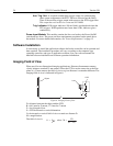
Interface Control Module: Depending on your system, either the TAXI or the
USB 2.0 Interface Control Module will be installed in the second from the left slot
(as you face the rear of the ST-133). This module provides the following functions:
• TTL In/Out Programmable Interface
• Communications Control (TAXI or USB 2.0 protocol)
Note: USB 2.0 protocol is supported by versions 2.5.14 and higher of
WinView/32 and WinSpec/32. PTG and USB 2.0 compatibility is supported by
versions 2.5.15 and higher.
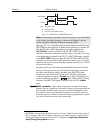
*
If using a PI-MAX camera with an ST-133 equipped with a PTG, there will be two cables
between the Controller and the Camera. The first goes from the Detector connector of the
Controller to the Power/Signal connector of the PI-MAX. The second cable goes from the
Timing Gen connector of the PTG to the Timing Gen connector of the PI-MAX.
Caution
WARNING