Chapter 2 Getting Started 19
for viewing on the video monitor with only a single-frame delay. An
associated zoom function provides 1x, 2x, or 4x viewing. At 1x, the
entire array image is displayed, but at reduced resolution (pixels are
discarded and fine detail could be lost). At 2x, the mapping is 1:1 and the
image portion selected by the Pan function is provided. The regions
overlap, allowing the entire array image to be examined with no loss of
resolution. At 4x, array pixels are enlarged so that a smaller part of the
array image is displayed as selected by the Pan function.
Once proper focus has been achieved, the user can transfer to normal data-
acquisition operation. The video output remains operative, but with a more
limited and fixed view because of the resolution limitation of RS-170 video.
Although this view is sufficient to cover the image from a small CCD array
in its entirety, it will not cover all the pixels from a large array. Instead, a
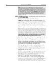
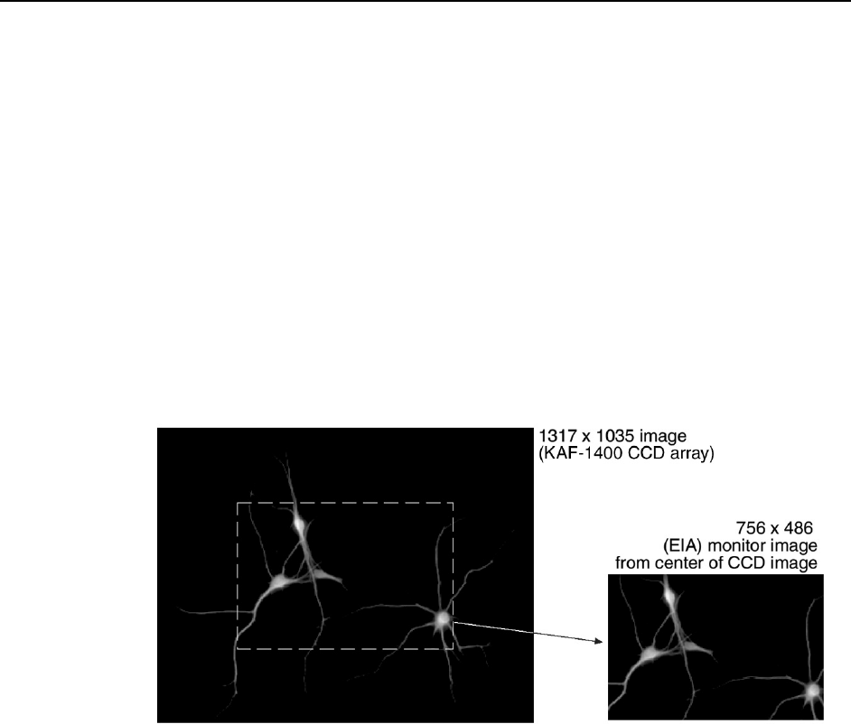
subset from the center of the image will be shown. For example, in the case
of the Kodak KAF-1400 (1317 x 1035), the monitor would display the
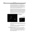
756×486 area from the center of the CCD image as shown in Figure 3.
Figure 3. Monitor Display of CCD Image Center Area
In post-acquisition processing the WinView/32 ROI (Region of Interest)
capability allows any portion of an acquired image to be displayed on the
computer monitor.
Again, note that the described video output behavior applies specifically
for the WinView/32 software only. Other application software may
provide different video output capabilities.
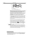
EXT SYNC BNC connector: This TTL input, which has a 10 kΩ pullup
resistor, allows data acquisition and readout to be synchronized with
external events. In the External Sync mode, readout is initiated when the
signal (typically a pulser trigger output) applied to the Ext Sync
connector is detected. Through software you can select either positive or
negative edge triggering (default = negative). See Chapter 5, Timing
Modes for detailed information.


