


Appendix H DIF Camera 97
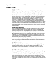
Images
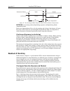
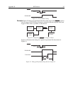
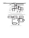
5 µs
Mechanical
Shutter
8 ms
8 ms
EXT. SYNC.
200 ns
NOTSCAN
5 µs
Image1 Image 2
~200 ns
Laser Output
>200 ns
Laser 1 Laser 2
READY
Figure 54. Timing Diagram for Typical IEC Measurement
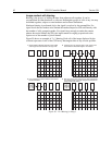
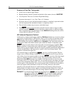
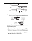
Figure 55 illustrates the interconnections that might be used for such an experiment
with two lasers. Figure 56 shows the timing for the two-laser experiment.
Delay Generator
(i.e.,DG535)
Camera
Head
Controller
ABC
EXT SYNC
Laser 2Laser 1
Sample
Volume
STOP
Computer
A DG535 can run at a
fairly slow rep rate or
use READY signal as
a trigger.
Figure 55. Setup for IEC Eexperiment with Two Lasers