


90 ST-133 Controller Manual Version 3.B
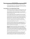
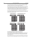
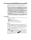
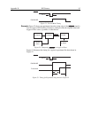
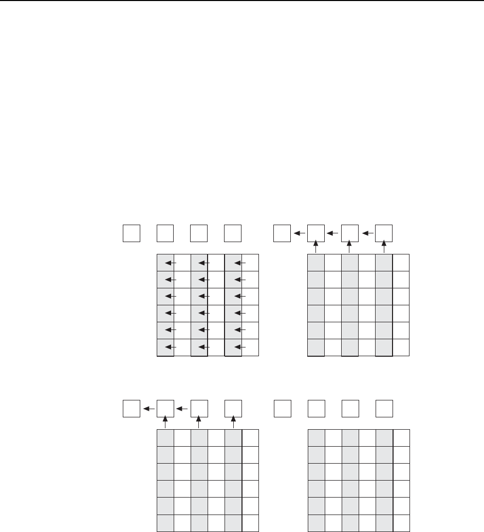
Part 2 of Figure 48 shows the situation early in the readout. The charge in the imaging
cells has been transferred to the adjacent storage cells and downshifting to the readout
register has started. Note that a new exposure begins immediately.
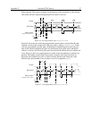
Part 3 of Figure 48 shows the transfer to the readout register continuing. The uppermost
two cells in each column are shown empty. Each row of charges is moved in turn into the
readout register and from there out of the array for further processing. The process
continues until all charges have been completely transferred out of the array. The imaging
cells continue accumulating charge throughout the readout process. Integrating in this
way while the readout takes place achieves the maximum possible time efficiency.
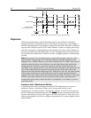
Part 4 of Figure 48 illustrates the situation at the end of the readout. The storage cells and
readout register are empty, but charge accumulation in the imaging cells continues until
the end of the programmed exposure.
43
12
Empty Readout Register. Exposure
has ended and image is being
transferred to storage cells.
Image has been shifted to storage cells, first
line has been shifted to Readout Register,
and second exposure begins.
Charge from first cell has been
shifted to the Output Node.
After first image is read out,storage cells are
empty. Second exposure continues.
A2
A1
B2
B1
A4
A3
B4
B3
A6
A5
B6
B5
C2
C1
C4
C3
C6
C5
A1 B1
C1
A2 B2
A4
A3
B4
B3
A6
A5
B6
B5
C2
C4
C3
C6
C5
D2
D1
E2
E1
D4
D3
E4
E3
D6
D5
E6
E5
F2
F1
F4
F3
F
6
F5
A1 B1
C1
A2 B2
A4
A3
B4
B3
A6
A5
B6
B5
C2
C4
C3
C6
C5
D2
D1
E2
E1
D4
D3
E4
E3
D6
D5
E6
E5
F2
F1
F4
F3
F
6
F5
D2
D1
E2
E1
D4
D3
E4
E3
D6
D5
E6
E5
F2
F1
F4
F3
F
6
F5
Figure 48. Overlapped Mode Exposure and Readout
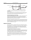
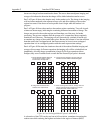
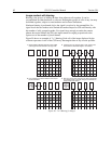
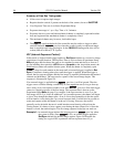
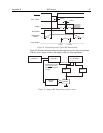
Non-Overlapped Operation Exposure and Readout
Figure 49 illustrates exposure and readout when operating in the non-overlapped mode.
Non-overlapped operation occurs automatically any time the exposure time is shorter
than the readout time. Figure 49 contains four parts, each depicting a later stage in the
exposure-readout cycle.
Part 1 of the figure shows the array early in the exposure. The imaging cells contain charge
proportional to the amount of light integrated on each of them. The storage cells are empty