


68 ST-133 Controller Manual Version 3.B
If burst pulsing is turned On, the T0 Output is deasserted when the last pulse
ensemble is completed.
Auxiliary Trigger Output: BNC,
AC-coupled pulse output. The
auxiliary timer's output is
available to the user through a
rear panel BNC for triggering
other system components. The
host software sets the Delay
Time of the auxiliary trigger
output with respect to the PTG
trigger time.
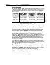
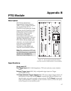
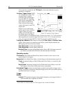
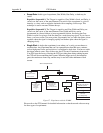
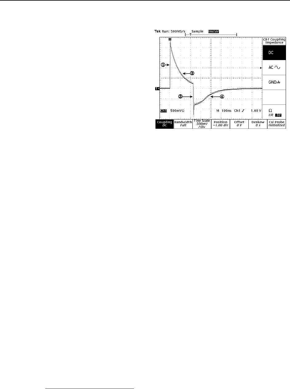
Figure 32 is an oscilloscope
screen capture of the Auxiliary
Trigger output. For proper
timing, users should trigger on
the leading edge of the output
Figure 32. Auxiliary Trigger Output
waveform (point 1 as indicated in Figure 32 and not at point 2, 3, or 4).Use positive-
edge triggering and a positive trigger level from +1.0 to +1.5 V. If using it to drive
logic, we suggest that the 74HCT or 74ACT logic-device families be used.
Timing Gen Interface: DB9 connector carrying the Start, Stop and Bracket Pulse
signals. These signals are connected to the head to control the photocathode and
MCP gating and are not directly available.
Gate Start pulse: switches photocathode On.
Gate Stop pulse: switches photocathode Off.
Bracket Pulse: In bracket pulsing On operation, biases MCP On; timing controlled
by software; asserted before Gate Start
*
and deasserted after Gate Stop.
Operating modes
Continuous: Pulse Width and Pulse Delay remain constant over the course of the
measurement for all triggers.
Sequential: Pulse Width, Pulse Delay, or both change as the measurement progresses.
Fixed: Incremental change in Pulse Width and/or Pulse Delay is constant for each
trigger.
Exponential: Incremental change in Pulse Width and/or Pulse Delay varies with
each trigger; well suited to fluorescence decay experiments.
Anticipated Trigger: Allows bracket pulsing operation with repetitive trigger source
having a fixed period. Hardware determines trigger period and starts bracket pulse at
specified interval prior to trigger.
Trigger
Modes:
Internal: PTG generates triggers at the specified frequency; each trigger initiates a
pulse ensemble that is applied to PI-MAX.
*
Value differs for each head (500 ns to 700 ns typical) and is stored in NVRAM.