


98 ST-133 Controller Manual Version 3.B
Images
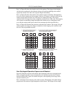
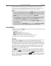
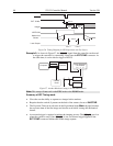
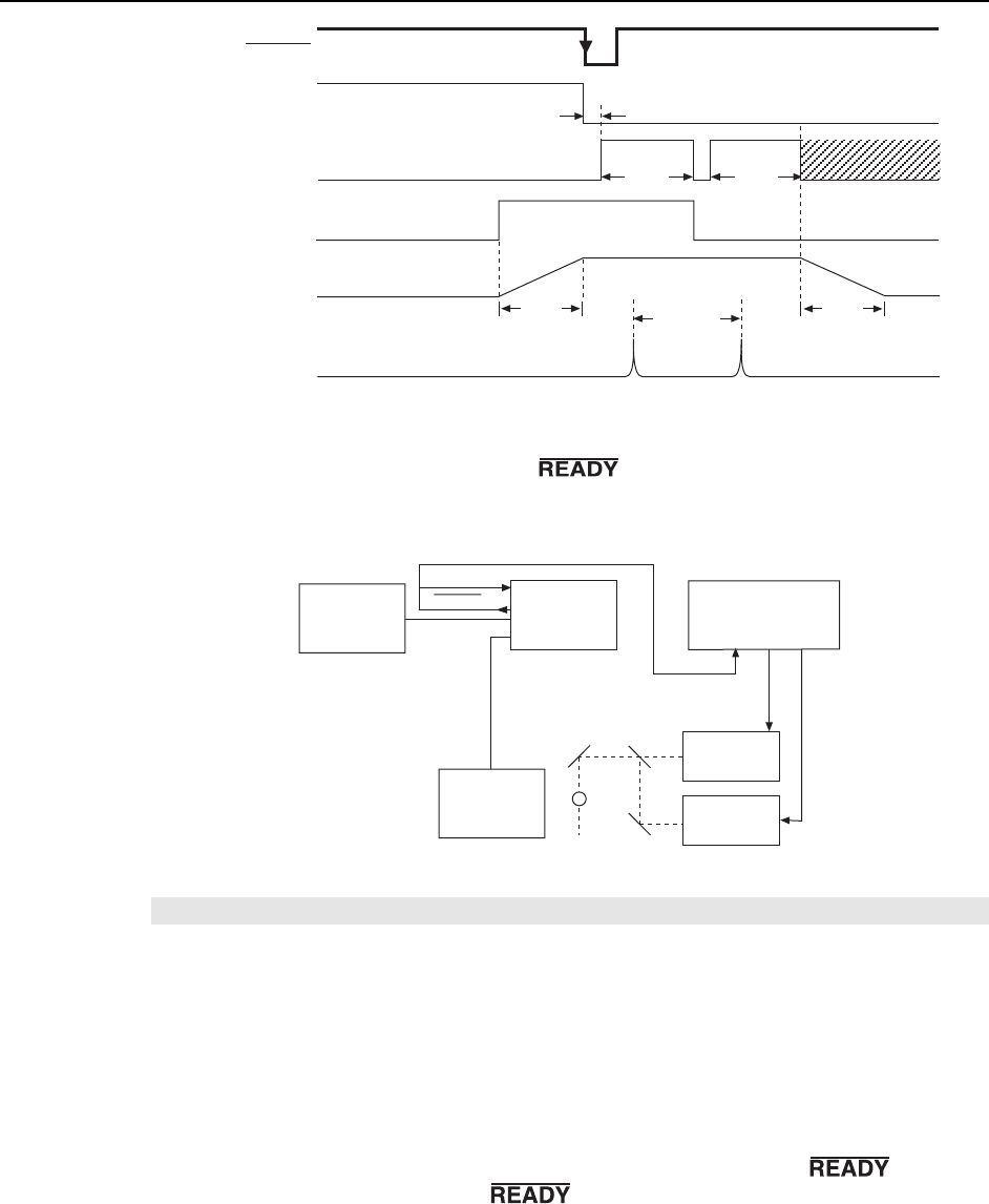
EXT. SYNC.
Mechanical
Shutter
8 ms
8 ms
NOTSCAN
Laser Output
Image 1 Image 2
5 µs 5 µs
Laser 1 Laser 2
>200 ns
200 ns
READY
Figure 56. Timing Diagram for IEC Experiment with Two Lasers
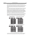
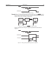
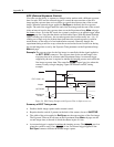
Example 2: As shown in Figure 57, the signal from the controller can be used
to trigger the controller by connecting it back into the EXT SYNC connector. At
the same time, it can be used to trigger a DG535.
Delay Generator
(i.e.,DG535)
Camera
Head
Controller
Ext.
AB
Laser 2
Laser 1
Computer
EXT SYNC
READY
Figure 57. Another Hardware Setup for an IEC Measurement
Note: This setup will not work in the EEC mode or the ESABI mode.
Summary of IEC Timing mode
• Gives the user the ability to capture two images before readout.
• Requires that the switch, if present on the back of the camera, be set to INACTIVE.
• The Exposure Time set in software on the Experiment Setup Main tab page becomes
the exposure time of the first image and also the wait before closing the mechanical
shutter.
• An external trigger is required to initiate the imaging process. The
goes low
when the system is ready. Once
is low, an external trigger applied to the
EXT SYNC connector initiates the double image capture.