


70 ST-133 Controller Manual Version 3.B
Operation
Introduction
Operation of the PTG module is quite simple. Most of the functions are performed
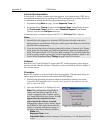
automatically through the backplane and the parameters are set via the Pulser Setup
screens of the host software (WinView/32 or WinSpec/32, version 2.4 and higher).
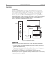
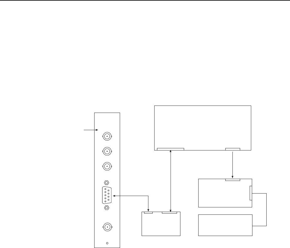
Operated in the External Trigger mode, a trigger is applied to the Ext. Trig. In
connector. No other connections to the PTG’s BNC connectors are required. When
operated in the Internal Trigger mode, unless a PTG output is used to trigger a peripheral
system component, no connections to the BNC connectors would be required at all.
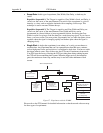
Figure 33 illustrates the connections in a typical system.
PTG
ST-133A Controller
Computer
High Speed
Serial Link
Spectrograph
(320PI)
GPIB
Timing
Gen
Signal/
Power
PI-MAX
EXT. TRIG. IN
PRE. TRIG. IN
TIMING GEN.
AUX. TRIG. OUT
TRIG.
Detector
Serial Comm
Trig IN
T0
6050-0369
6050-0336
Figure 33. Typical System Cabling
Handshakes
There are two possible conflicts that need to be avoided when pulsing an intensifier.
• To prevent artifacts from the laser from affecting the data, a readout should not be
initiated while the PTG is busy.
• Triggering the timing generator should be inhibited while a readout is in progress to
prevent high-voltage pulses from causing artifacts in the data.
The handshakes to accomplish these enabling/inhibiting operations take place
automatically, the necessary signals being exchanged via the backplane. No extra cabling
or operator intervention is required.