Installation
16 309301G
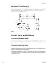
Mount the Fluid Panel(s)
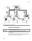
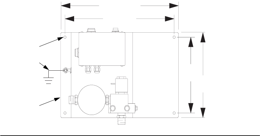
Mount the fluid panel(s) on a flat, sturdy surface. Install 1/4” or M6 fasteners in the four 0.28”
mounting holes (C1) and secure the fluid panel (C) to the mounting surface. Connect a
ground wire (G) as instructed on page 20.
Connect the Air and Fluid Lines
Fluid Panel 244599 and 244600
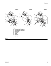
Connect the fluid supply line (11) to the 1/2” npt(f) meter inlet. See FIG. 5. Connect a fluid dis-
pense line (12) to the 1/2” npt(f) solenoid outlet. Connect the other end to the dispense valve
(9).
Fluid Panel 244601 and 246837
Connect an air supply line (8) to the 1/4” npt(f) solenoid valve port. The air supply must be fil-
tered to 10 micron to lengthen solenoid valve life.
Connect the fluid supply line (11) to the 1/4” npt(f) meter inlet. Connect a fluid dispense line
(12) to the 3/8” npt(m) outlet of the dispense valve on the fluid panel. Connect the other end to
the dispense valve (9).
FIG. 6
ti1357a
C1
C
13.4”
(315 mm)
12.4”
(340 mm)
8”
(203 mm)
9”
(229 mm)
G


