Service
309301G 39
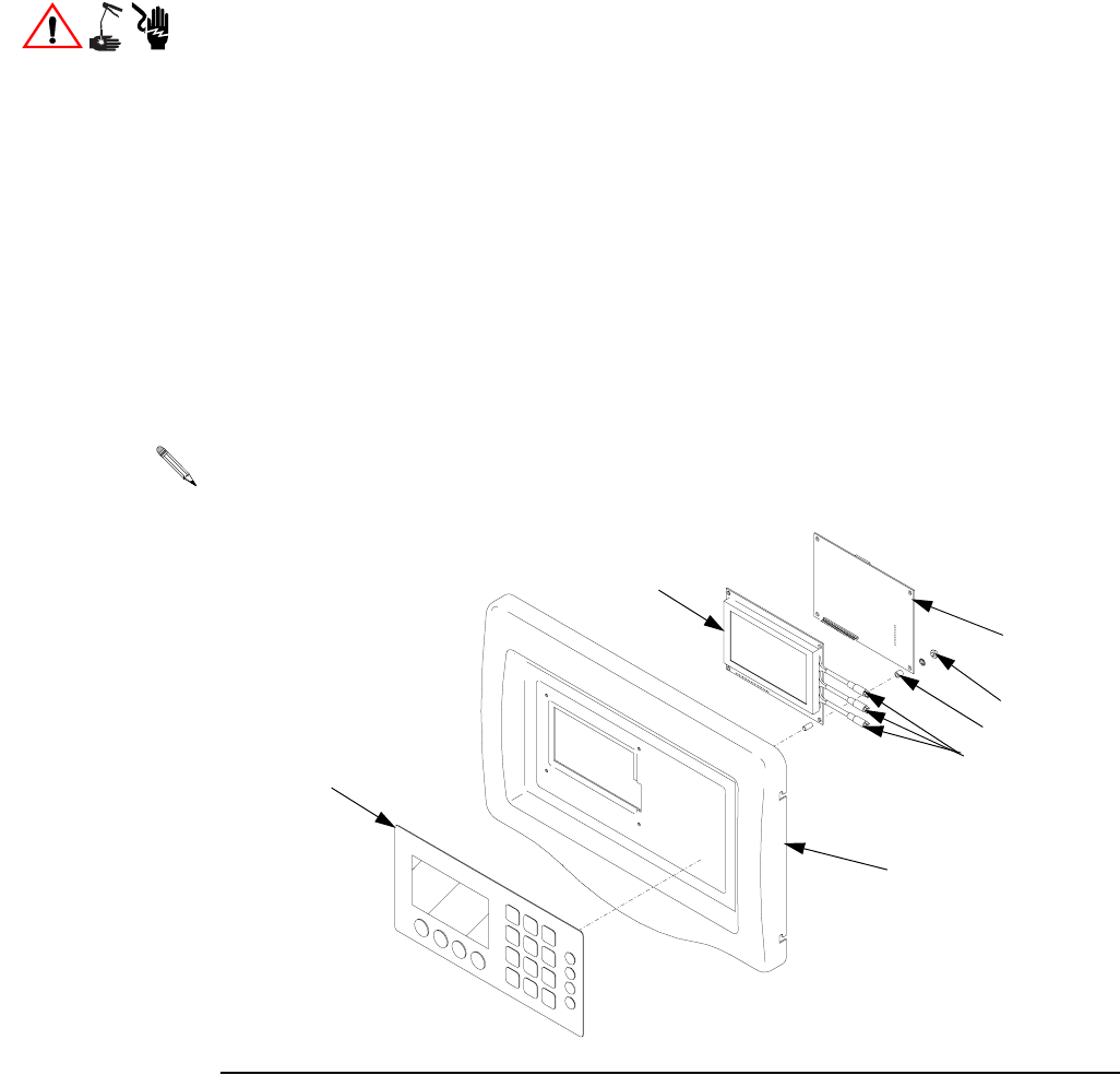
Replacing Display Board
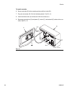
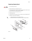
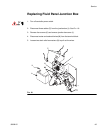
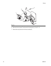
2. Remove controller cover (A). See page 37, steps 1-4.
3. Unplug keypad (D) ribbon cable from the display board. Note position of cable in connec-
tor. Arrow indicates pin #1, reconnect with pin #1 engaged.
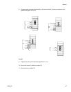
4. Remove four nuts (C1) from the board. See F
IG. 15.
5. Disconnect ground wire.
6. Unplug three fiber optic connectors (C3) from the diodes, then remove display board (F).
7. Install parts in reverse order of disassembly.
1. Turn off controller power switch.
• If replacing software chip, use a chip puller to remove it.
• Spacers (G) must be used in correct positions to protect the display and board.
FIG. 15
TI1056A
D
A
C3
C1
C
F
G


