Service
56 309301G
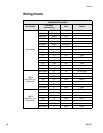
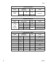
Wiring Charts
Control Box Wiring Chart
Wire / Harness
Connection
(Connector-Pin)
Color Function
Internal Wiring
Fuse 1 PWR SW 1A black
Fuse 2 PWR SW 2A black
PWR SW 1 P Supply L black
PWR SW 2 P Supply N black
GND TB P Supply G green/yellow
P Supply G P Supply - green/yellow
P Supply - J7-3 blue ground
P Supply + Fuse 3 blue
Fuse 3 J7-4 blue
J7-4 J7-1 blue jumper
J7-1 terminal block red 24 VDC power
J9-9 J9-10 blue jumper
J10-1 J10-2 blue jumper
J10-2 J10-3 blue jumper
J10-3 J10-4 blue jumper
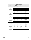
198556
Main PCB to 7 pin
bulkhead (1A)
terminal block P-1 red 24 VDC power
J9-5 P-2 red stop PB
P-3 open
J9-6 P-4 black start PB
J6-2 P-5 red solenoid
J6-1 P-6 black ground
ring terminal P-7 green ground
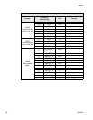
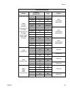
198556
Main PCB to 7 pin
Bulkhead (2A)
terminal block P-1 red 24 VDC power
J9-3 P-2 red stop PB
P-3 open
J9-4 P-4 black start PB
J6-4 P-5 red solenoid
J6-3 P-6 black ground
ring terminal P-7 green ground


