Fusion IV DVR User Guide
________________________________________________________________________________________________________
Document 800-05305V1 Rev B 21
10/11
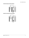
Rear Panel Connectors
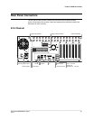
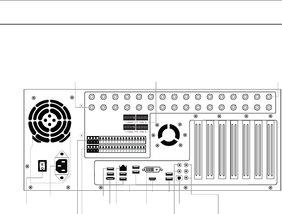
The rear panel of the recorder contains the connectors used to attach cameras,
sensors, and relays to the recorder. Below are diagrams that outline the location and
description of each connector.
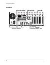
8/16 Channel
CH 1 in CH 2 in CH 3 in CH 4 in CH 5 in CH 6 in CH 7 in CH 8 in CH 9 in CH 10 in CH 11 in CH 12 in CH 13 in CH 14 in CH 15 in CH 16 in
1 2 3 4 5 6 7 8 9 10 11 12 13 14 15 16
CONTROL
1 2 3 4 5 6 7 8 9 10 11 12 13 14 15 1 6
COM
SENSOR
ON
OFF
ON
OFF
CH 1 Ou t CH 2 Out CH 3 Out CH 4 Ou t CH 5 Out CH 6 Out CH 7 Ou t CH 8 Out CH 9 Out CH 10 Out CH 11 Out CH 12 Out CH 13 Out CH 14 Out CH 15 Out CH 16 Out
AC power
Secondary power switch
Looping outputs (BNC) Looping output termination Video inputs (BNC)
Sensor inputsControl outputs
Optical output
5.1 Surround sound
USB USB HDMI
DVINetworkeSATA Line in – line level
Speaker out
Microphone in – not used
USB


