


12
•••••••••••••••••••••••••••••••••••••••••••••••••••••••••••••••••••••••••••••••••••••••••••••••••••••••••••••••••••••••••••••••••••••••••••••••••••••
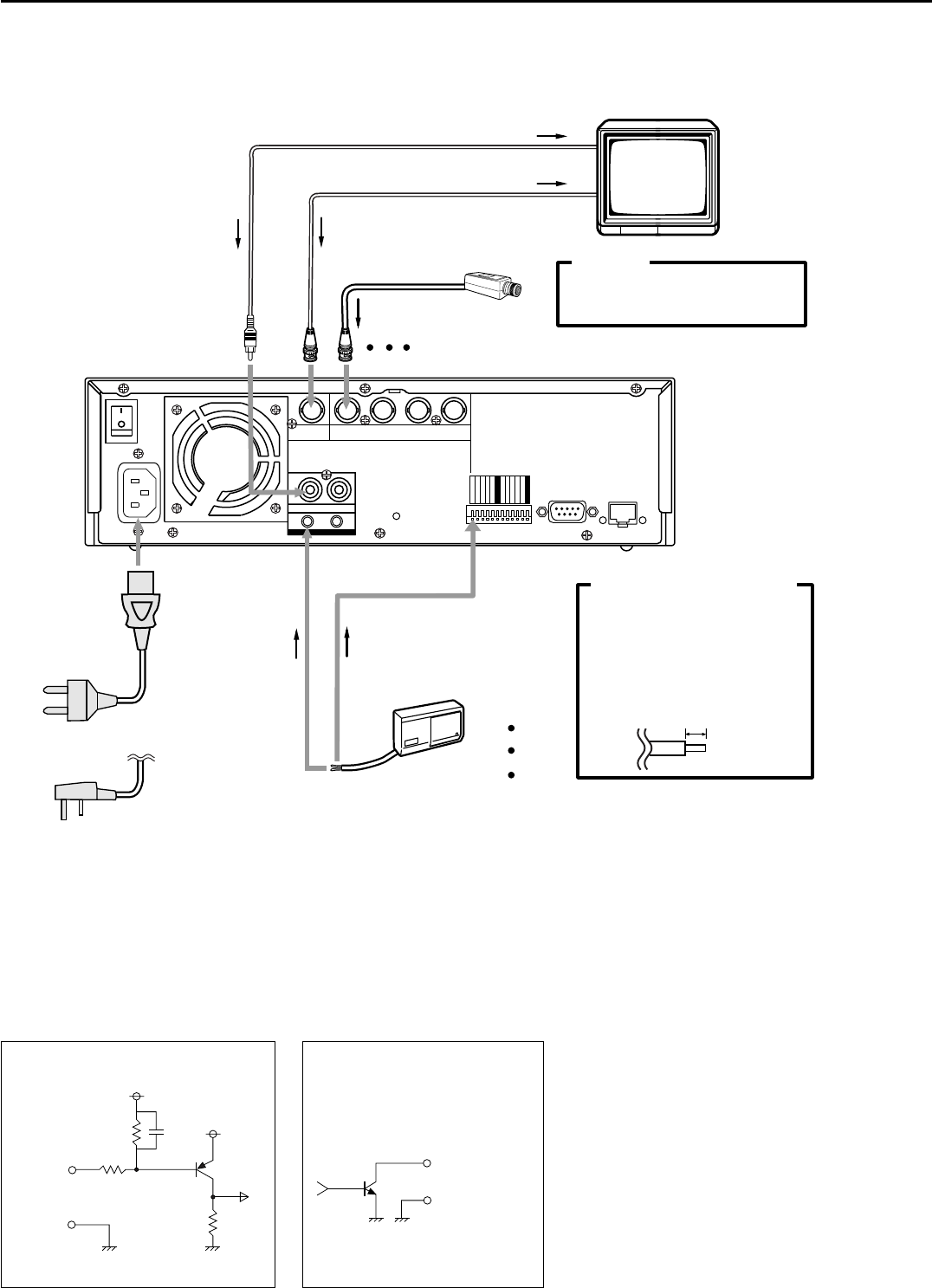
Connections
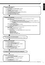
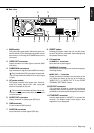
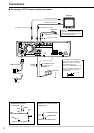
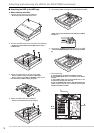
■ Connecting to CCTV camera, monitor, and sensor
1
MAIN
OFF
ON
AC IN
~
234
RESET
RS-232C
EMERGENCY
MODE OUT 1
MODE OUT 2
MODE OUT 3
MODE OUT 4
ALARM 1
ALARM 2
ALARM 3
ALARM 4
MODE OUT 5
GND
GND
CAMERA IN
INOUT
VIDEO
OUT
GND
AUDIO
100-240V
ETHERNET
MONITOR
POWER CORD
for U.K
for the Continent
To AUDIO IN connector
To VIDEO OUT connector
To VIDEO IN connector
To AUDIO OUT connector
To CAMERA IN 1 connector
CAMERA #1
Up to 4 cameras
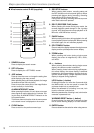
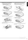
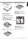
Processing the connecting line
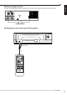
Connection on the ALARM IN
terminals and the I/O terminals
Compatible power lines
ø0.32 - ø0.65 mm (AWG 28 - 22)
Cut the designated area from the
electric wire’s outer covering
(vinyl portion).
5 - 7 mm
To GND
terminal
To ALARM IN terminal
corresponds to the
CAMERA #.
SENSOR #1
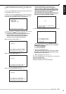
CAUTION
Connecting a coaxial transmission
camera incorrectly may damage the
input terminal. Be careful.
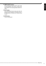
<Interface circuit inside the unit>
5V
5V
10kΩ
22kΩ
Input
terminal
0.047µF
GND
ALARM IN Input terminal
• Input Circuit
<Interface circuit inside the unit>
Output terminal
GND terminal
MODE OUT 1 to 5 Output terminal
• Output Circuit