


51
•••••••••••••••••••••••••••••••••••••••••••••••••••••••••••••••••••••••••••••••••••••••••••••••••••••••••••••••••••••••••••••••••••••••••••• Operations
ENGLISH
INFORMATION
For the relationship between the warning display and
CALL OUT signal output,
see page 81. The
warning display of the item written “Fixed” in the
CALL OUT output column displays unconditionally.
For the item written “Selectable” in the CALL OUT
output column, you can set the condition that CALL
OUT signal is output. For example, the buzzer can
be set to sound when reaching a value set in “HDD
MAIN REMAIN” or “HDD SUB REMAIN” of the
<CALL OUT SETTINGS> screen when “BUZZER”
in the <REAR TERMINAL SETTINGS> screen is
set to “WARNING.”
• HDD MAIN FULL/HDD SUB FULL
When the recordable HDD capacity becomes empty, a sig-
nal is output from the MODE OUT terminal which is set to
“CALL OUT” in <REAR TERMINAL SETTINGS> screen
and a “REC/FULL” appears on the screen for MAIN HDD.
(For SUB HDD, “REC/SUB FULL” appears.)
Setting (default: “OFF”)
“ON”: Outputs a signal when the recording capacity
becomes empty.
“
OFF”: Does not output a signal when the recording
capacity becomes empty.
1. Press the SET UP button
}
<SETTINGS>
}
<INITIAL
SET UP/INFORMATION>
}
<REAR TERMINAL SETTINGS>
}
Select “HDD MAIN FULL” or “HDD SUB FULL” in the <CALL
OUT SETTINGS> screen. Display the desired setting and
determine such setting.
2. Press the CLEAR button or the SET UP button.
♦ EMERGENCY REC DURATION
This item is used to set the recording time for emergency
recording.
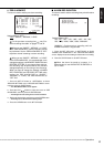
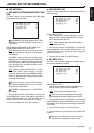
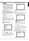
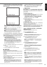
<REAR TERMINAL SETTINGS>
MODE OUT 1 OFF
MODE OUT 2 OFF
MODE OUT 3 OFF
MODE OUT 4 OFF
MODE OUT 5 OFF
KEY SOUND ON
BUZZER OFF
REMAIN HDD MAIN-10
%
CALL OUT SETTINGS
>>
EMERGENCY REC DURATION 10M
For the details concerning EMERGENCY
RECORDING settings,
see page 61.
Setting (default: “10M”)
“1M,” “2M,” “5M,” “
10M,” “20M,” “30M,” “60M”
1. Press the SET UP button
}
<SETTINGS>
}
<INITIAL
SET UP/INFORMATION>
}
Select “EMERGENCY REC
DURATION” in the <REAR TERMINAL SETTINGS> screen.
Display the desired setting and determine such setting.
2. Press the CLEAR button or the SET UP button.
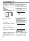
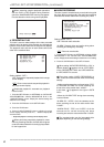
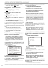
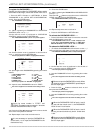
■ COMMUNICATION PORT SETTINGS
<COMMUNICATION PORT SETTINGS>
>>
RS-232C
ETHERNET
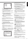
♦ RS-232C
This menu is used to set the communication device con-
nected to the RS-232C connector on this unit.
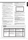
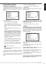
• MODE
This item is used to remotely control this unit via a PC con-
nected to the RS-232C terminal. Comments can also be
input via a PC and recorded along with the video.
<RS-232C>
>>
MODE REMOTE A
SETTINGS
Setting (default: “REMOTE A”)
“
REMOTE A”: Controls this unit via a PC and this
unit returns all the state information.
“REMOTE B”: Controls this unit via a PC and this
unit returns only the state transition information.
“REMOTE C”: Controls this unit via a PC and this
unit returns nothing.
“OFF”: Does not control this unit via a PC.
1. Press the SET UP button
}
<SETTINGS>
}
<INITIAL
SET UP/INFORMATION>
}
Select “MODE” in the <RS-232C>
screen. Display the desired setting and determine such setting.
2. Press the CLEAR button or the SET UP button.
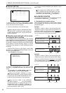
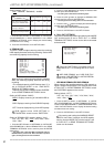
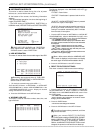
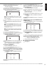
• RS-232C SETTINGS
This menu is used to set the RS-232C settings when setting
“MODE” above to “REMOTE A,” “REMOTE B,” or
“REMOTE C.”
<RS-232C SETTINGS>
>>
TRANSMISSION MODE 9600
DATA BIT LENGTH 8BIT
PARITY BIT NONE
STOP BIT LENGTH 1BIT
DELIMITER CR
Set all the settings to the same values as the
controlling PC.