


22
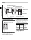
2-2 Connector Panel
Chapter 2 Location and Function of Parts
2-2 Connector Panel
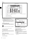
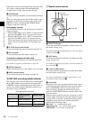
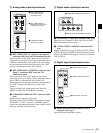
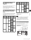
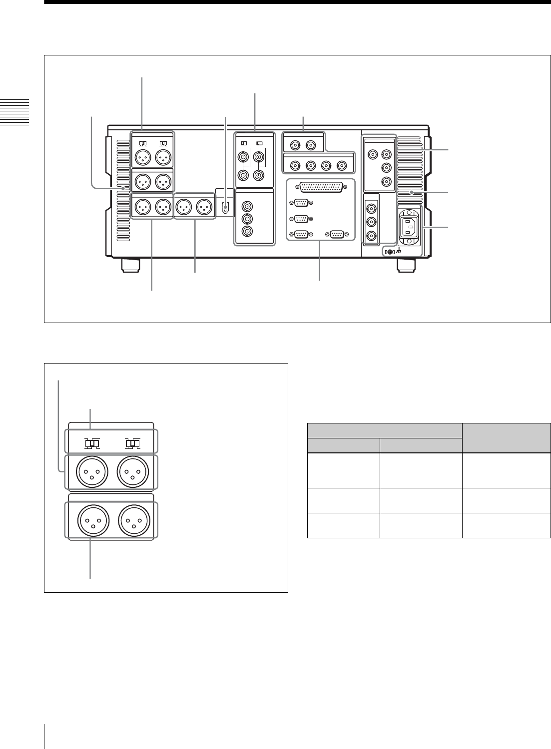
1 Analog audio input/output section
a AUDIO INPUT CH1 and CH2 (channels 1 and 2)
connectors (XLR 3-pin, female)
Input analog audio signals to channels 1 and 2.
You can record analog audio signals input to these
connectors to any audio track on tape.
b AUDIO INPUT CH1 and CH2 (channels 1 and 2)
LEVEL switches
Set these for each channel as shown in the following table,
according to the audio input levels and the impedance to
the AUDIO INPUT CH1 and CH2 connectors.
c AUDIO OUTPUT CH1 and CH2 (channels 1 and
2) connectors (XLR 3-pin, male)
Output analog audio signals for channels 1 and 2.
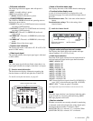
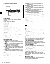
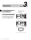
1 Analog audio input/output section (see page 22)
2 Analog video input/output section (see page 23)
3 Digital audio input/output section (see page 23)
4 Digital signal input/output
section (see page 23)
5 Power supply section
(see page 24)
6 External device connectors (see page 24)
7 Timecode input/output
section (see page 25)
8 Audio monitor signal output
section (see page 25)
Air inlet
Air outlet
HDV IN connector (OPTION)
(see page 25)
AUDIO INPUT
LOW
OFF
HIGH
ON
600Ω
CH1
LEVEL
LOW
OFF
HIGH
ON
600Ω
CH2
LEVEL
AUDIO OUTPUT
CH1 CH2
2 AUDIO INPUT CH1 and CH2 LEVEL switches
1 AUDIO INPUT CH1 and CH2 connectors
3 AUDIO OUTPUT CH1 and CH2 connectors
AUDIO INPUT CH1 and CH2 LEVEL switch settings
Audio input level and impedance Switch setting
Level Impedance
–60 dBu
(microphone
input)
High impedance
(approx. 20 kΩ)
LOW-OFF
(left position)
+4 dBu
(line audio input)
High impedance
(approx. 20 kΩ)
HIGH-OFF
(center position)
+4 dBm
(line audio input)
600 Ω HIGH-ON 600 Ω
(right position)