


84
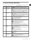
9-4 Items in the Extended Setup Menu
Chapter 9 Setup Menus
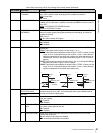
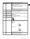
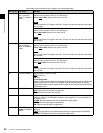
304 EDIT FIELD SELECT Select with which fields to start and end editing.
1F
: Start editing with field 1 and end with field 2.
2F: Start editing with field 2 and end with field 1.
1F/2F: Start and end editing depending on the timing of command reception.
Note
1F is always selected in PsF mode.
305 SYNC GRADE Select the target phase synchronization accuracy when editing in phase-
synchronized mode with menu item 004 set to “ON”.
ACCUR: ±0 frame accuracy
ROUGH: ±1 frame accuracy
306 DMC INITIAL SPEED Select the initial speed automatically set in DMC editing.
MANU
: The speed determined by the rotation of the search dial
PLAY: Normal playback speed
STILL: Stationary
±0.03 to ±1, +2: Speed set in this range (select from +2, ±1, ±0.5, ±0.2, ±0.1, ±0.03)
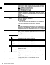
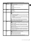
307 AUTO-DELETION FOR
INCONSISTENT DATA
Select the operation of this unit when an erroneous edit point is set.
MANU
: A warning is given by flashing the name of the edit point button for the
erroneous edit point in the lower control panel.
Delete or correct the erroneous edit point manually.
NEG&E: When edit points are set incorrectly, such as when an OUT point is before
an IN point, or an audio OUT point is before an audio IN point, or when too
many edit points are specified, the previously set edit point is deleted
automaically.
NEG: When edit points are set incorrectly, such as when an OUT point is before an
IN point, or an audio OUT point is before an audio IN point, the previously set
edit point is deleted automaically. When too many edit points are specified, a
warning is given by flashing the name of the edit point button for the
unnecessary edit point in the control panel.
Note
Pressing the button corresponding to an edit point to be deleted and the DELETE
button simultaneously deletes the edit point. Editing is not executed if an
erroneous edit point is set (the name of an edit button is flashing).
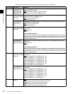
309 SERVO/AV REFERENCE
SEL
Select the servo reference signal.
AUTO1
: During recording, the input video signal is used as the servo reference
signal. During playback, the signal selected by F2 (REF VID) in function menu
page P03: VID PROC is used as the servo reference signal. If the signal
selected by the F2 (REF VID) in function menu page P03: VID PROC is not
connected, an internal reference signal is used.
AUTO2: When F2 (REF VID) in function menu page P03: VID PROC is set to
“REF”, and any of F2 (INS TC), F3 (INS CUE), and F5 (ASSEMBLE) to F10
(INS A4) in function menu page P07: E.PRESET is lit, the reference signal for
video/audio signal processing is locked to the input video signal.
EXT: The servo reference signal is forced to be “EXT” (an external reference video
input signal is used).
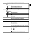
Menu items in the range 300 to 399, relating to editing operations (Continued)
Item number Item name Settings