


27
3-2 Reference Sync Signals
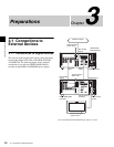
Chapter 3 Preparations
3-2 Reference Sync
Signals
This section describes how reference signals for the video
output signals and servo system are selected.
The output from the internal reference video signal
generator is supplied to the output video signal and servo
circuits as a reference signal.
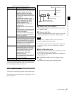
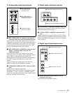
3-2-1 Selecting Reference Sync
Signal Depending on Operational
Status
The reference sync signal selection switches automatically
between REF and INPUT depending on the menu settings
and the operating status of the unit, as shown in the
following table.
a) EE: In E-E mode
PB: Playing back (normal playback, jog mode, shuttle mode, variable
speed mode and stop mode)
EDIT: Edit preset enabled
REC: Recording
• When there is no HDSDI signal input whereas INPUT is
selected, the unit synchronizes with the REF signal.
• When there is no REF signal input whereas REF is
selected, no external reference signal is used. In this
case, the unit synchronizes with the internally generated
reference signal.
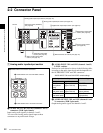
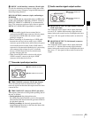
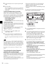
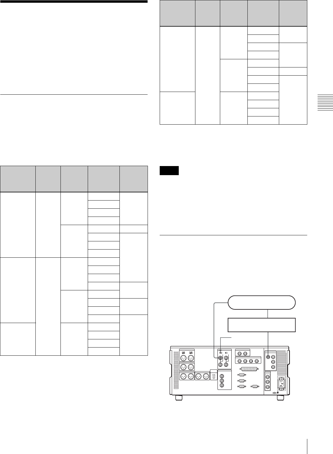
3-2-2 Connecting Reference Signals
Connect reference signals as shown below, according to
the way in which the unit is to be used.
• Connections for recording from a switcher or
signal generator
P03:VID
PROC
F2(REF VID)
setting
Menu
item
309
setting
Menu
item 334
setting
Unit’s
operational
status
a)
Reference
signal
setting
– EXT NORMAL EE REF
PB
EDIT
REC
INPUT EE INPUT
PB REF
EDIT
REC
REF AUTO1 NORMAL EE
PB
EDIT
REC INPUT
INPUT EE
PB REF
EDIT
REC INPUT
INPUT – EE
PB
EDIT
REC
REF AUTO2 NORMAL EE REF
PB
EDIT INPUT
REC
INPUT EE
PB REF
EDIT INPUT
REC
INPUT – EE
PB
EDIT
REC
Notes
P03:VID
PROC
F2(REF VID)
setting
Menu
item
309
setting
Menu
item 334
setting
Unit’s
operational
status
a)
Reference
signal
setting
HDSDI
INPUT
REF. VIDEO
INPUT
75Ω termination
switch: ON
Reference signal
Switcher or signal generator
HDW-1800/D1800