34
4-1 Recording
Chapter 4 Recording and Playback
5
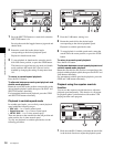
Until all the digits are set as required, repeat steps 3
and 4.
6
Select F9 (SET).
When F3 (TCG RUN) in function menu page P02: TC
is set to “FREE”, the timecode value starts advancing
immediately.
To set the timecode value to the real time
With the items in function menu page P02: TC set as
follows, carry out the procedure of “Setting an initial
timecode value”. In steps 3 and 4, set a value slightly after
the current time as the initial value, then carry out step 6 at
the instant the real time catches up with the setting.
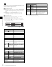
F1 (TCG SRC): INTERNAL
F2 (TCG MODE): PRESET
F3 (TCG RUN): FREE
F4 (DROP FRM): DF (59.94i, 29.97PsF mode only)
To set a user bit value
The user bit values recorded on the timecode track provide
for eight hexadecimal digits, which can be used to hold the
date, time, or other information.
Use the following procedure.
In function menu page P02: TC, select and set F1 (TCG
SRC) to “INTERNAL” and F2 (TCG MODE) to
“PRESET”, respectively.
1
In function menu page P01: HOME, set F8
(COUNTER) to “UB”.
2
Carry out the procedure in steps 2 to 6 under the
heading above, “Setting an initial timecode value”.
Set values, using the hexadecimal digits 0 to 9 and A
to F.
If any of the settings of “REC START MARK MODE” in
setup menu item 631 is set to “ON” (to write a recording
start mark), then the user bits are overwritten with the shot
mark data for 20 frames from the start of recording in crash
record mode, assemble edit mode, or insert edit mode.
For details on the setup menu, see Chapter 9 “Setup
Menus”.
To synchronize the internal timecode
generator with an external signal
Use this method to synchronize the timecode generators of
multiple VTRs, or to record the playback timecode signal
from an external VTR without deterioration of the signal
waveform.
In this case the RUN and DF settings are ignored.
You can synchronize the internal timecode generator with
either of the following external timecodes.
• The timecode output (LTC) of an external timecode
generator or external VTR connected to the TIME
CODE IN connector of the unit
• The timecode (LTC or VITC) in the HDSDI signal input
to the unit
To synchronize the internal timecode generator with an
external signal, use the following procedure.
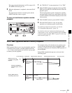
1
Set “TCG REGEN MODE” in setup menu item 605 to
“TC&UB” or “TC”.
2
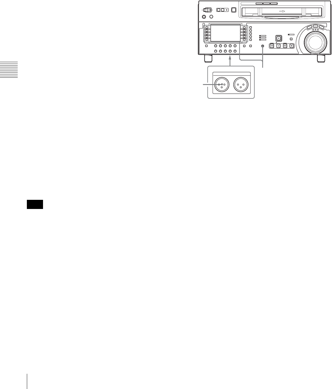
To synchronize with an external timecode signal input
to this unit’s TIME CODE IN connector, connect an
external timecode generator or external VTR's
timecode output to the TIME CODE IN connector.
To synchronize with a timecode data contained in an
HDSDI signal input to this unit, set F1 (VIDEO IN) to
“SDI” in function menu page P01: HOME.
3
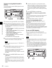
Set the timecode generator items as follows.
To synchronize with an external timecode signal
input to this unit’s TIME CODE IN connector:
• In function menu page P02: TC, set F1 (TCG SCR)
to “EXT LTC”.
To synchronize with the LTC data contained in an
HDSDI signal input to this unit:
• Set F1 (TCG SRC) to “SDI IN”.
• Set F2 (TCG MODE) to “RGN:LTC”.
To synchronize with the VITC data contained in an
HDSDI signal input to this unit:
• Set F1 (TCG SRC) to “SDI IN”.
• Set F2 (TCG MODE) to “RGN:VITC”.
The unit starts the internal timecode generator running
in synchronization with the external timecode
generator.
The internal timecode generator is synchronized, and
even if the external timecode generator is
Note
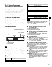
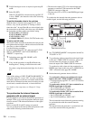
1,2,3
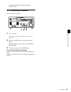
TIME CODE
IN OUT
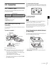
1
TIME CODE IN connector


