


77
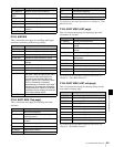
9-3 Items in the Basic Setup Menu
Chapter 9 Setup Menus
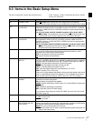
9-3 Items in the Basic Setup Menu
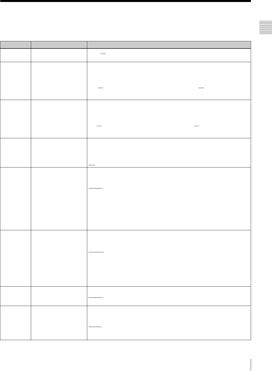
The basic setup menu contains the following items. In the “Settings” column of the table, the factory default
settings are underlined.
Item number Item name Settings
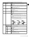
001 PREROLL TIME 0S to 5S
to 30S: Set the preroll time in the range from 0 to 30 seconds.
A preroll time of at least 5 seconds is recommended when using this unit for editing.
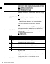
002
a)
CHARACTER
H-POSITION
Adjust the horizontal position of the character information output from the
COMPOSITE VIDEO OUTPUT 3 (SUPER) connector, SDI OUTPUT 3 (SUPER)
connector, or HDSDI OUTPUT 3 (SUPER) connector for superimposed display on
the monitor.
0 to 1E
to 3C (59.94i, 29.97PsF, 23.98PsF mode)/0 to 1B to 36 (50i, 25PsF,
24PsF mode): The hexadecimal value 00 is for the far left of the screen and
increasing the value moves the position of the characters to the right.
003
a), b)
CHARACTER
V-POSITION
Adjust the vertical position of the first line of the character information output from
the COMPOSITE VIDEO OUTPUT 3 (SUPER) connector, HDSDI OUTPUT 3
(SUPER) connector, and SDI OUTPUT 3 (SUPER) connector for superimposed
display on the monitor.
0 to 57
to 6C (59.94i, 29.97PsF, 23.98PsF mode)/0 to 70 to 88 (50i, 25PsF, 24PsF
mode): The hexadecimal value 00 is for the top of the screen and increasing
the value lowers the position of the characters.
004 SYNCHRONIZE When editing using this unit as a controller and an external VTR connected to this
unit via a 9-pin remote control cable, this item determines whether or not to
operate the two units in phase synchronization.
OFF: Do not operate in phase synchronization.
ON
: Operate in phase synchronization.
005 DISPLAY INFORMATION
SELECT
Determine the type of text information to be output from the COMPOSITE VIDEO
OUTPUT 3 (SUPER), SDI OUTPUT 3 (SUPER) and HDSDI OUTPUT 3 (SUPER)
connector when F5 (CHARA) is set to “ON” in function menu page P04: MISC-1.
T&STA
: Time data display information and the unit’s status
T&UB: Time data display information and the user bits
T&CTL: Time data display information and CTL
T&T: Time data display information and timecode (LTC or VITC)
TIME: Timecode (LTC or VITC) only
If there is an overlap between the setting of this item and the setting of the control
panel, it is automatically avoided. For example, if CTL is selected on the control
panel and this menu item setting is “T&CTL”, then CTL and LTC are output.
006 LOCAL FUNCTION
ENABLE
Determine which buttons on the control panel are enabled when this unit is
controlled from external equipment.
DIS: All buttons and switches are disabled.
S&E&P
: Only the STOP button, EJECT button, P1 to P5 and DISPLAY buttons are
enabled.
ENA: All buttons and switches are enabled.
MAP: Follow the LOCAL KEY MAP setting.
For information about setting the LOCAL KEY MAP, see menu item 023 “LOCAL
KEY MAP” (page 78).
007 TAPE TIMER DISPLAY Determine whether to display the CTL count in 12-hour mode or 24-hour mode.
+ –12H
: 12-hour mode
24H: 24-hour mode
008 MONITORING
SELECTION FOR VTR-
TO-VTR EDIT
For two-VTR editing with the monitor connected only to the recorder, determines
whether the recorder is forced into E-E mode when the recorder’s PLAYER button
is pressed to view the player’s playback signals on the monitor.
MANU
: Do not force the recorder into E-E mode.
AUTO: Set the recorder to E-E mode, so that the playback signals of the player are
output to the video monitor.