


29
3-4 Superimposed Character Information
Chapter 3 Preparations
3-4 Superimposed
Character Information
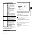
When F5 (CHARA) in function menu page P04: MISC-1
is selected, the video signal output from the HDSDI
OUTPUT 3 (SUPER), SDI OUTPUT 3 (SUPER) or
COMPOSITE VIDEO OUTPUT 3 (SUPER) connector
can contain superimposed text information, including
timecode, menu settings, and alarm messages.
To adjust the character display
You can adjust the position, size and type of the
superimposed characters using setup menu items 002, 003,
005, 009, and 011.
For details, see Section “9-3 Items in the Basic Setup
Menu” (page 77).
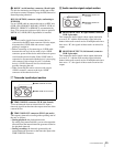
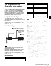
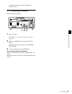
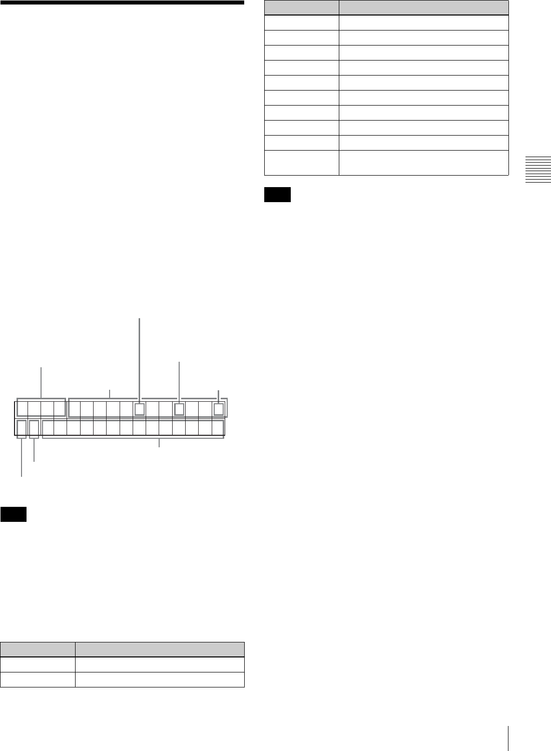
Information displayed
The display shown above corresponds to the factory
default settings of the unit.
Changing the setting in setup menu item 005 displays
different time data in the lower line of the display.
For details, see Section “9-3 Items in the Basic Setup
Menu” (page 77).
a Type of time data
If the time data or user bits cannot be read correctly, they
will be displayed with an asterisk. For example, “T*R”,
“U*R”, “T*R.” or “U*R.”.
b Timecode reader drop-frame mark (for 59.94i,
29.97PsF mode only)
“.”: Indicates drop-frame mode
“:”: Indicates non-drop-frame mode
c Timecode generator drop-frame mark (for 59.94i,
29.97PsF mode only)
“.”: Indicates drop-frame mode (factory default setting)
“:”: Indicates non-drop-frame mode
d VITC data field mark
“ ” (blank): Fields 1 and 3 (for 59.94i, 29.97PsF mode) or
fields 1, 3, 5 and 7 (for 50i, 25PsF mode)
“ * ”: Fields 2 and 4 (for 59.94i, 29.97PsF mode) or fields
2, 4, 6 and 8 (for 50i, 25PsF mode)
e VTR control mode (Recorder/player selection)
The indication changes as follows, according to the VTR
control mode (the setting of F6 (R/P SEL) in function
menu page P06: EDIT).
P: Two-unit editing is currently being carried out and the
VTR (player) connected by a 9-pin remote cable is
being operated from the lower control panel (P-
CTRL).
R: Two-unit editing is currently being carried out and this
unit (recorder) is being operated from the lower
control panel (R-CTRL).
No indication: This unit (recorder) is being operated from
the lower control panel as a standalone unit.
Alternatively, multiple VTR units connected by 9-pin
remote cables are being operated in synchronization
(PARARUN).
Note
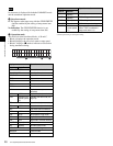
Display Meaning
CTL CTL counter data
TCR LTC reader timecode
TCR . 23 : 59 . 40 . 18 *
PSHUTTLESTILL
1 Type of time data
2 Timecode reader drop-frame mark
(for 59.94i, 29.97PsF mode only)
3 Timecode generator
drop-frame mark (for
59.94i, 29.97PsF
mode only)
4 VITC data
field mark
5 VTR control mode
7 Operation mode
Time data
6 Stop freeze mode
UBR LTC reader user bits
TCR. VITC reader timecode
UBR. VITC reader user bits
TCG Timecode generator timecode
UBG Timecode generator user bits
IN IN point
OUT OUT point
AI Audio IN point
AO Audio OUT point
DUR Duration between any two of the four edit
points (IN, OUT, audio IN, audio OUT)
Note
Display Meaning