


Installing the Equipment
Page 2-10 Instruction Manual: evolution 5000 E57xx DSNG and DENG Voyager Encoder
ST.TM.E10076.3
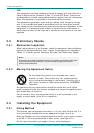
WARNING…
THE POWER-SUPPLY CABLE SHOULD BE ROUTED SO THAT IT IS NOT LIKELY TO BE
DAMAGED OR TRAPPED BY ITEMS PLACED UPON OR AGAINST IT, PAYING PARTICULAR
ATTENTION TO THE CABLE AT CONNECTION POINTS.
DC Power Connector (Encoder)
The wires in the dc power cable are coloured in accordance with the wire
colour code shown in Table 2.2.
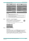
Table 2.2: DC Input Connector and Cable details
Plug/Socket Wire Colour Voltage Condition
Jaeger C type
Pin 1: Green/Yellow or Green Earth/Vehicle frame
Pin 2: Brown or Red +V
Pin 3: Blue or Black -V
2.6 Signal Connections For the Basic Unit
2.6.1 Introduction
All signal connectors are located at the rear panel of the Encoder. For a
detailed interface specification see Annex B, Technical Specification.
Always use the specified cables supplied for signal integrity and compliance
with EMC requirements (see Annex B, Technical Specification).
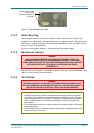
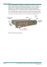
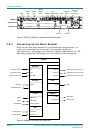
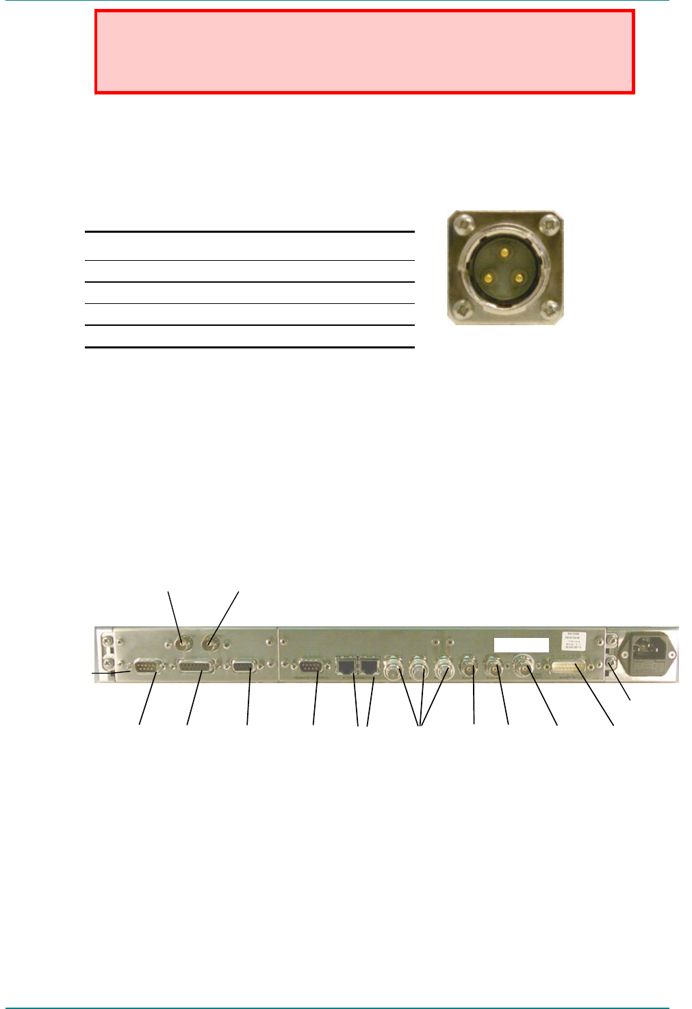
Figure 2.3: E5714 (1U) Rear Panel Component Parts and Connectors
Option Slot 2
Audio In and
Audio
Reference Out
H Sync Composite
Video
ASI Outputs
EthernetRS-232
Data
RS-422
Data
Alarm
RS-232/
RS-485
Control
SDI In
Base Board
Technical Earth
IF Out Main
IF Out Monitor
1
2
3