Installing the Equipment
Page 2-16 Instruction Manual: evolution 5000 E57xx DSNG and DENG Voyager Encoder
ST.TM.E10076.3
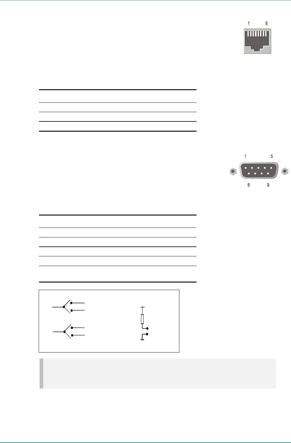
Ethernet #1 and #2
An 8-way, RJ-45 connector provides a 10BaseT
Ethernet interface for communications with the MEM
for control and monitoring. The Encoder has a single
switched Ethernet channel. Ethernet#1 is selected as
default at power-up. If a carrier is not detected on
Ethernet#1 then the input switches to Ethernet#2.
This gives a redundant Ethernet control via two hubs.
Table 2.8: Ethernet Connector
Pin Signal Pin Signal
1 Tx Out (+) 4-5 Not connected
2 Tx Out (-) 6 Rx In (-)
3 Rx In (+) 7-8 Not connected
Alarm
If required, connect an external status monitoring
device to the ALARM connector.
A 9-way, D-type male connector provides an alarm
relay interface which can be used to send a signal to
remote equipment.
Table 2.9: Alarm Connector
Pin Signal Pin Signal
1 Ground 6 Fail (NO)
2 Fail (common) 7 Fail (NC)
3 Alarm (NO) 8 Alarm (common)
4 Alarm (+) (NC) 9 Reset 2 (internally grounded)
5 Reset 1 (internally pulled
to 3.3 V via 10 kW)
NOTE…
NC = Normally Closed, NO = Normally Open, and refers to the relay contacts. Refer to Annex B,
Section B.4.3, Alarm for details of the relay contact rating.
Alarm
Common
Fail (NC)
Fail (NO)
Alarm (NC)
Alarm (NO)
Fail
Common
Reset 1
Reset 2
3.3 V
10 kW


