


The next 40 bytes are for Analyzer 1 Data Information.
Byte Position
21 1 byte - Machine data mode, one of the following decimal values:
−1 = off
0 = state data without tags
1 = state data with each chip assigned to a machine
(2kB memory) and either time or state tags
2 = state data with unassigned pod used to store tag data
(4kB memory)
8 = state data at half channel (8kB memory with no tags)
10 = conventional timing data at full channel
11 = transitional timing data at full channel
12 = glitch timing data
13 = conventional timing data at half channel
14 = transitional timing data at half channel
22 1 byte - Unused.
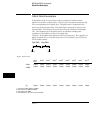
23 2 bytes - List of pods in this analyzer, where a binary 1 indicates that the
corresponding pod is assigned to this analyzer
bit 15 bit 14 bit 13 bit 12 bit 11 bit 10 bit 9 bit 8
unused unused always 1 unused unused unused unused Pod 8
1
bit 7 bit 6 bit 5 bit 4 bit 3 bit 2 bit 1 bit 0
Pod 7
1
Pod 6
2
Pod 5
2
Pod 4
3
Pod 3
3
Pod 2Pod 1unused
1 – also unused in the 1661A, 1662A, and 1663A
2 – also unused in the 1662A and 1663A
3 – also unused in the 1663A
Example xx10 0000 0001 111x indicates pods 1 through 4 are assigned to this
analyzer (x = unused bit).
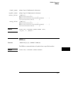
25 1 byte - This byte returns which chip is used to store the time or state tags
when an unassigned pod is available to store tag data. This chip is available
in state data mode with an unassigned pod and state or time tags on. Byte 21
= 2 in this mode.
DATA and SETup Commands
Data Preamble Description
26–7