


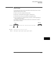
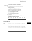
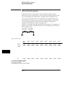
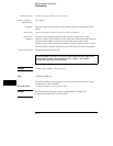


Byte Position
clock
lines
Pod 8
1
Pod 7
1
pod 6
2
pod 5
2
pod 4
3
pod 3
3
pod 2 pod 1
4
177
2 bytes 2 bytes 2 bytes 2 bytes 2 bytes 2 bytes 2 bytes 2 bytes 2 bytes
195
2 bytes 2 bytes 2 bytes 2 bytes 2 bytes 2 bytes 2 bytes 2 bytes 2 bytes
..........
..........
..........
(x)
2 bytes 2 bytes 2 bytes 2 bytes 2 bytes 2 bytes 2 bytes 2 bytes
2 bytes
1 – unused in the 1661A, 1662A, and 1663A
2 – also unused in the 1662A and 1663 A
3 – also unused in the 1663A
4 – The headings are not a part of the returned data.
Row (x) is the highest number of valid rows specified by the bytes in byte
positions 101 through 126 in all modes and when neither analyzer is in glitch
mode. In the glitch mode, row (x) is the larger of:
1. The highest number of valid rows specified by the bytes in byte
positions 101 through 126; or,
2. 2048 + the highest number of valid rows for the pods assigned to
the timing analyzer, when one or more glitches are detected.
The clock-line bytes for the 1660A, which also includes 2 additional data lines
(D), are organized as follows:
xxxx xxPN xxDD MLKJ
The clock-line bytes for the 1661A and 1662A are organized as follows:
xxxx xxxx xxxx MLKJ
The clock-line bytes for the 1663A are organized as follows:
xxxx xxxx xxxx xxKJ
DATA and SETup Commands
Acquisition Data Description
26–11