


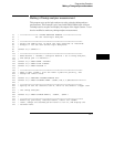

Making a Timing analyzer measurement
This program sets up the logic analyzer to make a simple timing analyzer
measurement. This example can be used with E2433-60004 Logic Analyzer
Training board to acquire and display the output of the ripple counter. It can
also be modified to make any timing analyzer measurement.
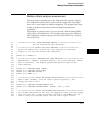
10 ! ****************** TIMING ANALYZER EXAMPLE ******************
20 ! for the 1660A Logic Analyzer
30 !
40 ! **************************************************************
50 ! Select the module slot in which the logic analyzer is installed.
60 ! Always a 1 for the 1660-series logic analyzers.
70 !
80 OUTPUT 707;":SELECT 1"
90 !
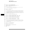
100 ! **************************************************************
110 ! Name Machine 1 "TIMING," configure Machine 1 as a timing analyzer,
120 ! and assign pod 1 to Machine 1.
130 !
140 OUTPUT 707;":MACH1:NAME ’TIMING’"
150 OUTPUT 707;":MACH1:TYPE TIMING"
160 OUTPUT 707;":MACH1:ASSIGN 1"
170 !
180 ! **************************************************************
190 ! Make a label "COUNT," give the label a positive polarity, and
200 ! assign the lower 8 bits.
210 !
220 OUTPUT 707;":MACHINE1:TFORMAT:REMOVE ALL"
230 OUTPUT 707;":MACH1:TFORMAT:LABEL ’COUNT’,POS,0,0,#B0000000011111111"
240 !
250 ! **************************************************************
260 ! Specify FF hex for resource term A, which is the default trigger term
for
270 ! the timing analyzer.
280 !
290 OUTPUT 707;":MACH1:TTRACE:TERM A, ’COUNT’, ’#HFF’"
300 !
310 ! ***************************************************************
320 ! Remove any previously inserted labels, insert the "COUNT"
330 ! label, change the seconds-per-division to 100 ns, and display the
340 ! waveform menu.
Programming Examples
Making a Timing analyzer measurement
36–3