1-6 Dell PowerEdge 4200 Systems Service Manual
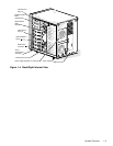
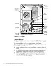
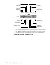
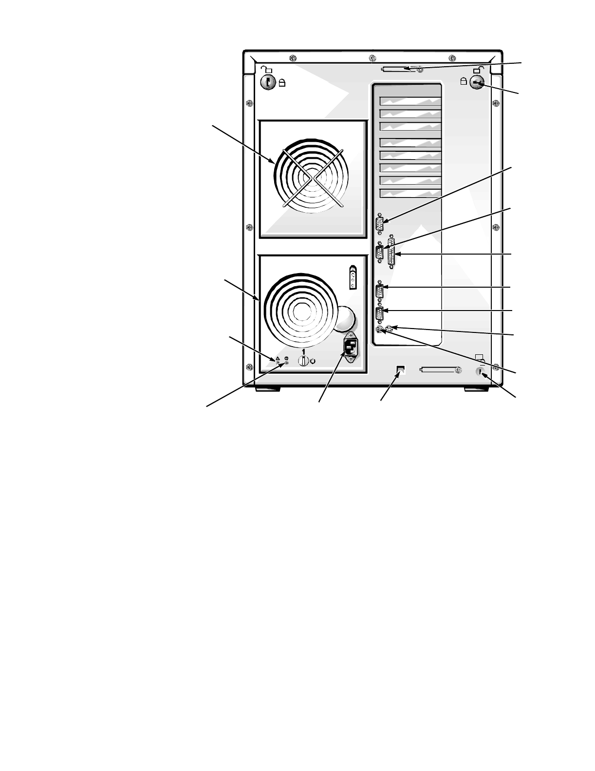
Figure 1-5. I/O Panel
System Memory
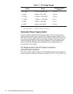
The PowerEdge 4200 systems have a minimum of 64 MB of 72-bit-wide, buff-
ered EDO memory. The system memory capacity can be expanded to 512 MB
by using combinations of 32- and 128-MB buffered, EDO DIMMs.
The system board has eight 168-pin DIMM sockets. The socket population rules
for the DIMMs are as follows:
•
Populate the DIMM sockets in order from DIMM_A (upper) to DIMM_H
(lower).
•
The DIMMs should be obtained from Dell to guarantee compatibility. All
system memory operates at the speed of the slowest DIMM installed.
•
DIMMs of both capacities can be installed in the system. However, the
larger-capacity DIMMs should be installed in the top sockets, beginning
with socket DIMM_A, with the smaller-capacity DIMMs installed after-
wards in order toward socket DIMM_H.
keylocks (2)
parallel port
connector
AC power receptacle
serial port 1
connector
mouse
connector
keyboard
connector
serial port 2
connector
video
connector
server-
management
serial port
connector
security
cable slot
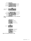
power supply
(optional) or
cooling fan
SMB connector
power-supply
fault LED (red)
power-supply
online LED
(green)
SCSI
connector
power supply


