


1-10 Dell PowerEdge 4200 Systems Service Manual
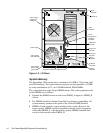
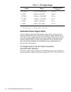
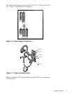
Redundant Power Supply Option
Systems with the optional redundant power supply feature contain a power-
supply paralleling board and a second 700-watt power supply module. In this
case, the two power supply modules each provide part of the power for the sys-
tem and are hot-pluggable (either power supply module can be removed and
replaced while the system is online and operational).
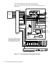
Power distribution dia-
grams for both the redundant and nonredundant power configurations are
provided later in this chapter.
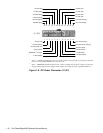
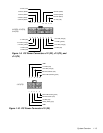
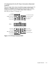
Pin Assignments for the DC Power Connectors
(Nonredundant Systems)
The power-supply output voltages for nonredundant systems can be measured
at the connectors on the back of the power supply (P1, P2, P3, P4, and P5) or at
Table 1-1. DC Voltage Ranges
Voltage Range
Maximum Output
Current
1
+3.3 VDC +3.135 to +3.465 VDC 15.0 A
+5 VDC +4.90 to +5.25 VDC 50.0 A
+12 VDC +11.40 to +12.60 VDC 25.0 A
–12 VDC –10.80 to –13.20 VDC 0.3 A
–5 VDC –4.50 to –5.50 VDC 0.3 A
+5 VFP
2
+4.85 to +5.36 VDC 0.25 A
1
Maximum continuous DC output power shall not exceed 700 W.
2
VFP (volts flea power) — sometimes called “standby power.”