


1-14 Dell PowerEdge 4200 Systems Service Manual
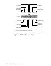
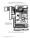
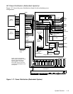
DC Power Distribution (Nonredundant Systems)
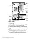
Figure 1-11 shows the power distribution system for the nonredundant system
configuration.
Figure 1-11. Power Distribution (Nonredundant System)
NOTE: A server management cable (16-
pin) carries the +5 VFP from the system
board to the SCSI backplane. The control
panel cable (30-pin) carries the +5 VFP
from the backplane to the control panel.
power
supply # 1
+5 VFP
PSON#
–5 VDC
+12 VDC
–12 VDC
+5 VDC
+3.3 VDC
+5 VFP
PSON#
–5 VDC
+12 VDC
–12 VDC
+5 VDC
+3.3 VDC
+12 VDC
+5 VDC
+3.3 VDC
+12 VDC
+5 VDC
+3.3 VDC
+12 VDC
+5 VDC
+12 VDC
+5 VDC
P1
P2
P3
DDBP
FD1–4
SCSI backplane (six drive bays)
FLOPPY
1
2345
6
CD-ROM
control panel
speaker
power-on
LED
on/off
reset
3 X 6 LEDs
system board
power
management
logic
RTC/
NVRAM
PWRGOOD
EISA1
through
EISA3
PCI4
through
PCI8
–12 VDC
+12 VDC
–5 VDC
+5 VDC
+5 VFP
+3.3 VDC
PSON#
PWR-
+3.3 VDC
+5 VDC
+12 VDC
–12 VDC
–5 VDC
+12 VDC
–12 VDC
+5 VDC
battery
battery (+3 VDC)
+3.3 VDC
PWR-
+5 VFP
SMB
Backplane
processor
core
regulator (2)
main memory
sockets
DIMM_A
through
DIMM_H
PROCESSOR1
and
PROCESSOR2
KEYBOARD
MOUSE
FAN 1
through
FAN 5
+3.3 VDC
core VCC (+2.1 to +3.5 VDC)
fuse
+12
VDC
+5 VDC
+5 VDC
GTL
regulator
+1.5 VDC
P6 signal terminators
P1–5
power
connector
panel
+5 VFP from SCSI
+5 VFP to SCSI
backplane
NRLED