


Removing and Replacing Parts 4-19
using the information recorded before you removed the system board. Recon-
figure the expansion card(s) using the EISA Configuration Utility.
S
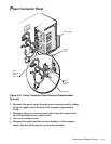
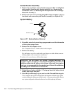
ystem Board Components
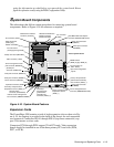
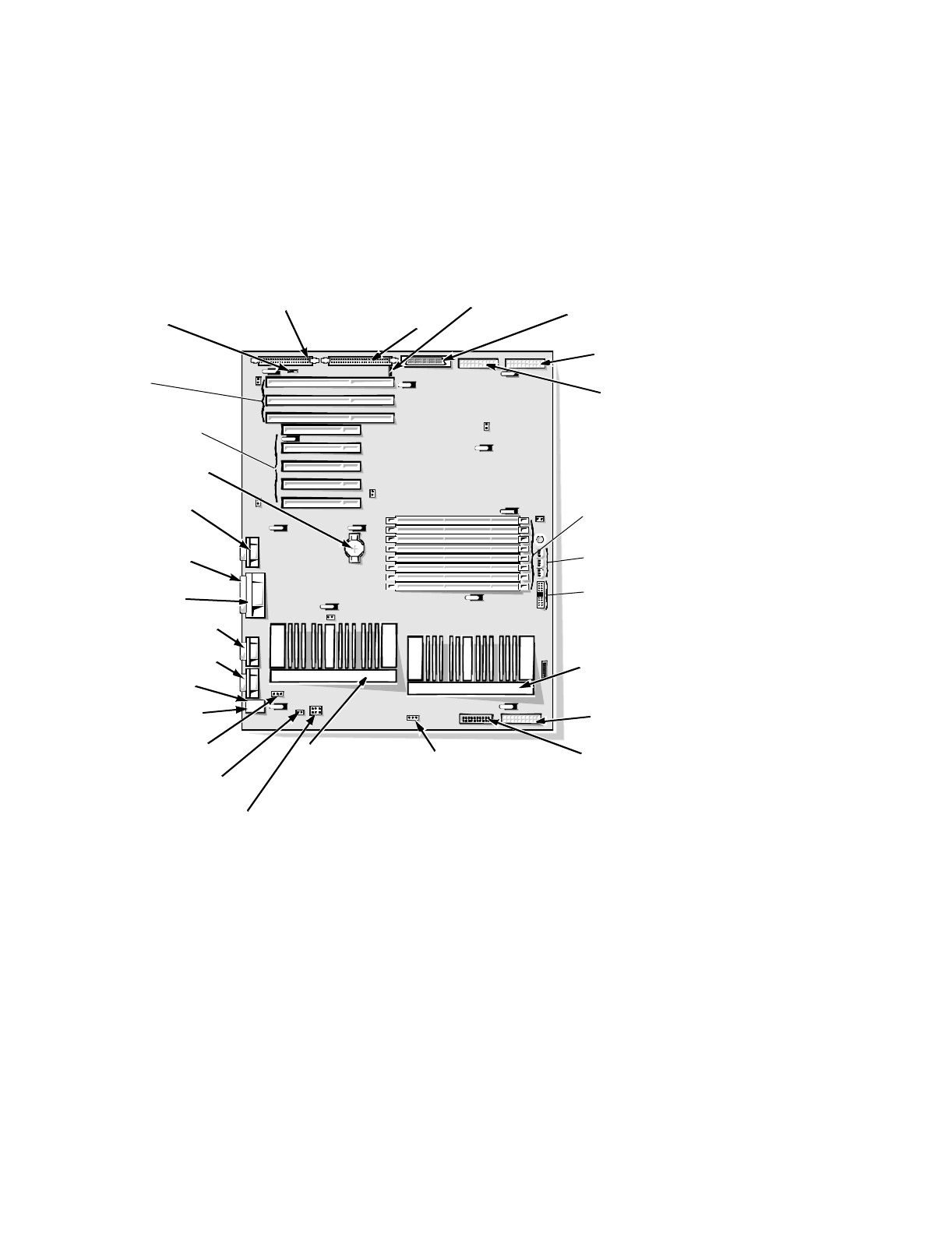
The subsections that follow contain procedures for removing system board
components. Refer to Figure 4-18 for reference as required.
Figure 4-18. System Board Features
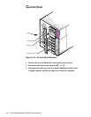
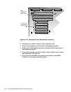
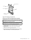
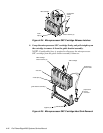
Expansion Cards
The PowerEdge 4200 contains a total of eight expansion slots as shown in Fig-
ure 4-19. An opening is provided in the back of the chassis for each expansion
card connector. Connectors EISA1 through EISA3 (top three connectors) sup-
port 32-bit master or slave cards.
Connectors PCI4 through PCI8 support 32-bit PCI cards. Video expansion
boards should be installed in one of the three primary PCI card slots (PCI6,
PCI7, or PCI8).
video connector (JVGA)
parallel port
connector (PARALLEL)
serial port connector (SERIAL2)
serial port connector (SERIAL1)
mouse connector (MOUSE)
keyboard connector (KYBD)
diskette-drive interface
connector (FLOPPY)
secondary
microprocessor
guide bracket
assembly and
connector (PROC_2)
battery connector (BATTERY)
Ultra/Narrow SCSI host
adapter connector
(SCSI2 CD-ROM)
Ultra/Wide SCSI host adapter
connector (BACKPLANE SCSI1)
server-management bus
connector (SMB BACKPLANE)
server-management serial
port connector (REMOTE)
DIMM sockets
(DIMM_A [top]–DIMM_H)
speed and configuration
jumpers
fan connectors (3)
(FAN1–FAN3)
front of system board
primary microprocessor
guide bracket assembly
and connector (PROC_1)
EISA connectors
(EISA1 [top],
EISA2, and EISA3)
PCI connectors
(PCI4 [top] through PCI8)
secondary microprocessor
temperature sensor (TEMP_2)
intrusion alarm
connector (INTRUSION)
primary microprocessor
temperature sensor
(TEMP_1)
fan connector (FAN5)
fan connector
(FAN4)
external server-management
bus connector (SMB EXTERNAL)
power input connector
(POWER1)
power input connector
(POWER2)
power input connector
(POWER3)