


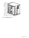
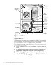
System Overview 1-13
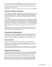
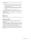
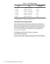
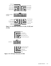
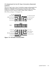
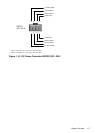
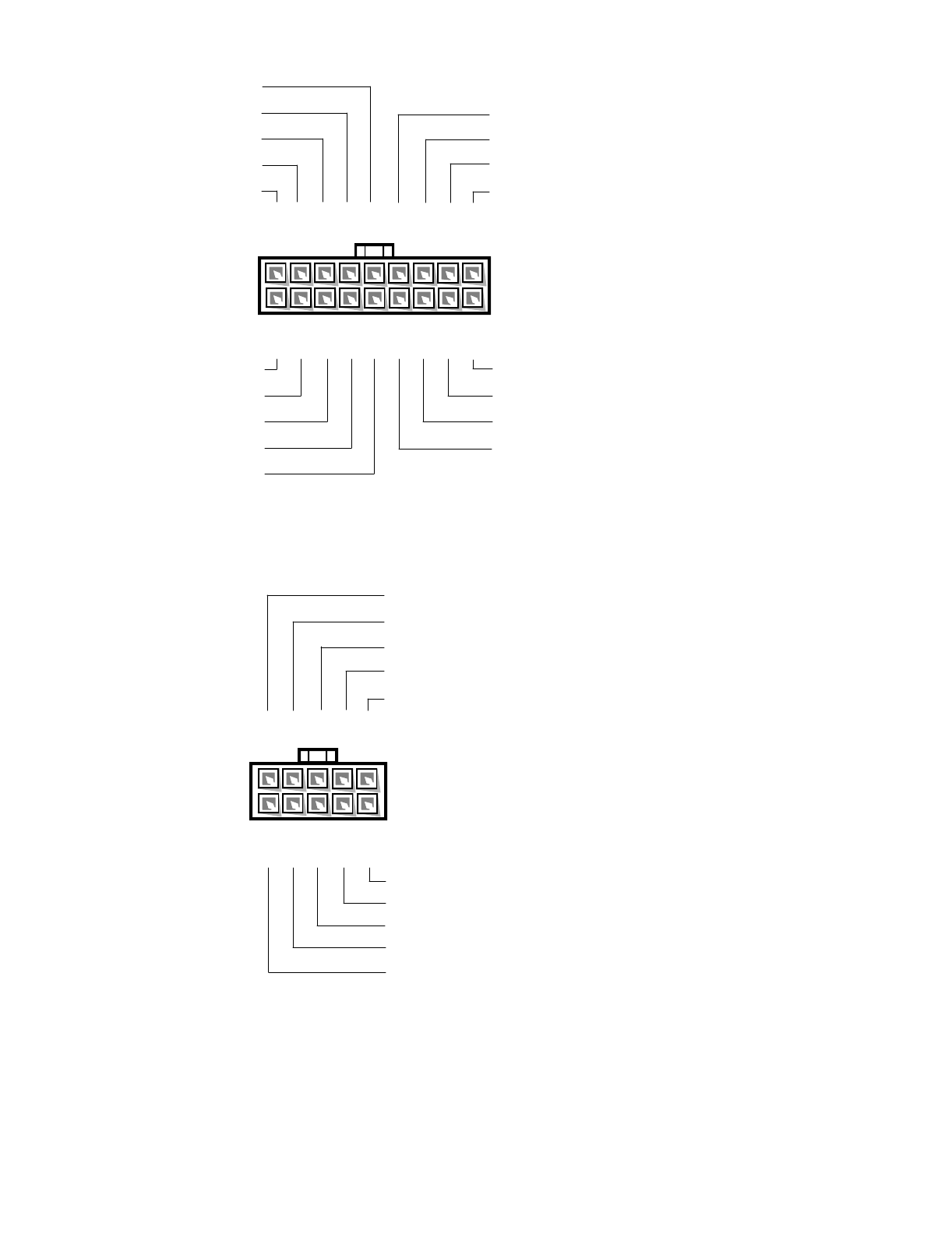
Figure 1-9. DC Power Connectors J12 (P2), J13 (P3), and
J14 (P4)
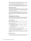
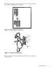
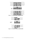
Figure 1-10. DC Power Connector J15 (P5)
1234567
+5 VDC (red)
+12 VDC (yellow)
+3.3 VDC (orange)
89
+3.3 VDC (orange)
+3.3 VDC (orange)
+5 VDC (red)
+5 VDC (red)
+12 VDC (yellow)
+5 VDC (red)
J12 (P2), J13 (P3),
J14 (P4)
10 11 12 13 14
15 16
+5 VDC (red)
common (black)
common (black)
common (black)
+5 VDC (red)
17 18
common (black)
common (black)
common (black)
common (black)
23 4 5
Good LED anode (green)
Fail LED anode (red)
+5 VDC (red)
+FAN_TACH (gray)
J15 (P5)
1
678910
+3.3 VDC (orange)
+SW1
+SW1
+12 VDC (red)
Good LED cathode (green)
Fail LED cathode (red)