


System Overview 1-11
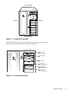
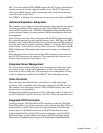
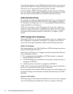
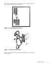
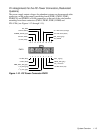
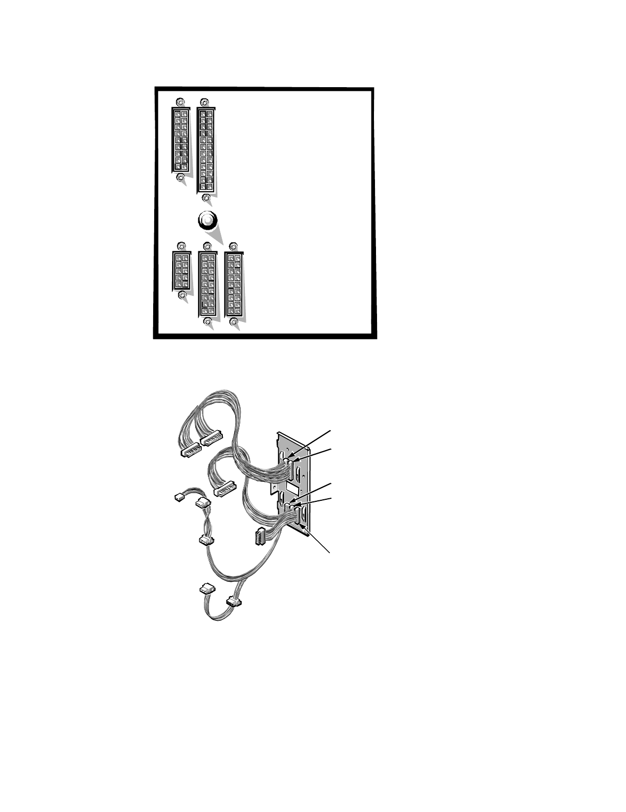
the connectors on the power connector panel (J11, J12, J13, J14, and J15). Fig-
ures 1-6 and 1-7 show both sets of connectors.
Figure 1-6. Power Supply Connectors
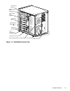
Figure 1-7. Power Connector Panel
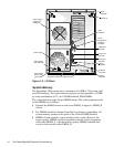
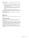
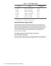
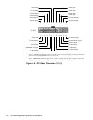
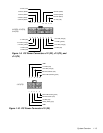
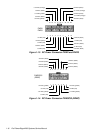
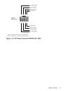
Figures 1-8 through 1-10 show the pinouts for the five DC power connectors,
J11 through J15.
P1
P2
P4 P3
P5
J11 (P1)
J12 (P2)
J13 (P3)
J14 (P4)
J15 (P5)