


System Overview 1-15
Pin Assignments for the DC Power Connectors (Redundant
Systems)
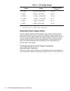
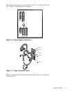
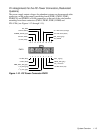
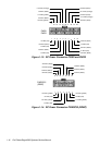
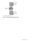
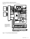
The power-supply output voltages for redundant systems can be measured at the
connectors on the power-supply paralleling board (PWR1, PWR2, PWR3,
PWRSCSI, and PWRFD) or at the connectors on the end of the wire bundles
extending from these connectors (PWR1, PWR2, PWR3, DDBP, and
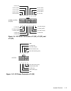
FD1–FD4) (see Figures 1-12 through 1-15).
.
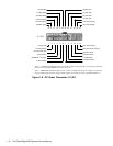
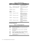
Figure 1-12. DC Power Connector PWR1
1234567
-12 VDC (blue)
PWR_STAT_BIT (gray)
-5 VDC (white)
89
NC_+12 sense
BAT_V (gray)
I
2
C_SDA (gray)
I
2
C_SCL (gray)
PRES_DET (gray)
+5 VDC sense (red)
PWR1
10 11 12 13 14
15 16
NC_NRLED
common (black)
POWER_GOOD (gray)
common (black)
NC_3INH
17 18
+5 VFP (violet)
+3.3 VDC sense (orange)
FAN_TACH (gray)
-3.3 VDC sense (black)