


System Overview 1-17
1
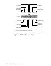
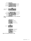
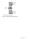
Wires 1 through 4 are connected to FD1 and FD2.
2
Wires 5 through 8 are connected to FD3 and FD4.
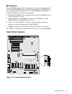
Figure 1-15. DC Power Connector PWRFD (FD1–FD4)
234
1
+5 VDC (red)
PWRFD
(FD1–FD4)
1
567
8
2
+12 VDC (yellow)
common (black)
common (black)
+12 VDC (yellow)
common (black)
common (black)
+5 VDC (red)