


System Overview 1-9
regardless of whether you are installing internal or external devices, use the fol-
lowing guidelines:
•
A single SCSI device (such as the standard CD-ROM drive) is terminated.
•
If two or more SCSI devices are installed, connect the devices as follows:
—
Attach one of the devices to the end connector on the SCSI cable, and leave the
terminator enabled on that device.
—
The other end of the SCSI cable connects to the computer’s built-in Ultra/Narrow
SCSI host adapter or to an optional SCSI host adapter card, which needs no
termination.
—
Disable the terminators on all other devices you attach to the cable.
The standard SCSI CD-ROM drive is configured as the last device on the SCSI
cable. Therefore, any additional devices attached to the cable should have their
terminators disabled.
See the documentation provided with the SCSI device for information on dis-
abling the device’s terminator.
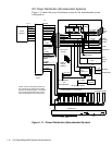
S
ystem Unit
The following subsections provide service-related information about the system
unit.
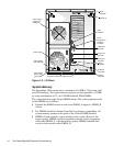
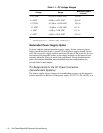
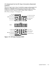
System Power Supply
The PowerEdge 4200 system contains either one 700-watt power supply (non-
redundant configuration) or two 700-watt power supplies (redundant
configuration).
Each installed power supply can operate from an AC power source of 90 to 265
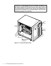
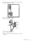
VAC at 50 or 60 Hz. When the red LED on a power supply is lit (except during
start-up), it indicates that the power supply has failed (see Figure 1-5). When
the green LED is lit, it indicates that +5 VDC is on. The system power supply
provides the DC operating voltages and currents listed in Table 1-1.
NOTE: The power supply produces DC voltages only under its loaded condi-
tion. Therefore, when you measure these voltages, the DC power connectors
must be connected to their corresponding power input connectors on the system
board or drives.
.