


1-12 Dell PowerEdge 4200 Systems Service Manual
1
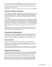
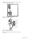
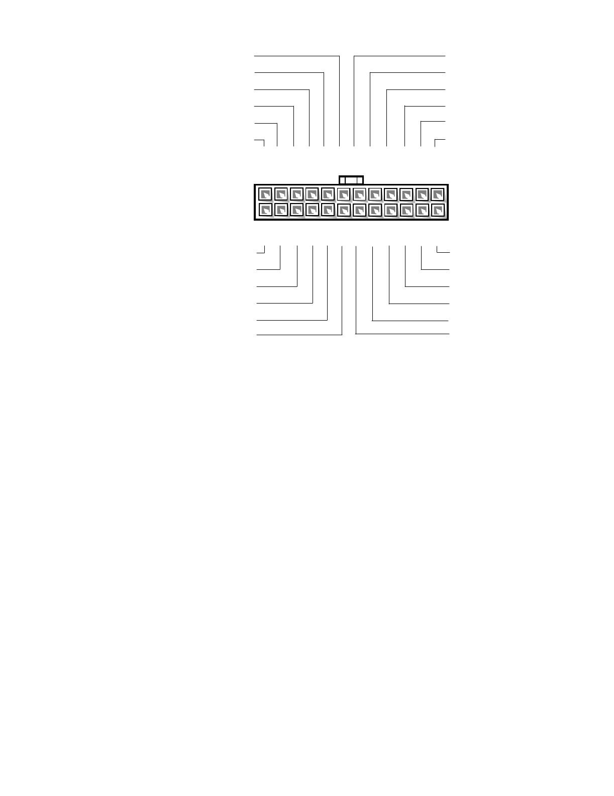
Pin 13 — PSON# should measure between +4 and +5 VDC except when the power button on the front
panel is pressed, taking PSON# to its active-low state.
2
Pin 5 — PWRGOOD should measure between +4 and +5 VDC when the power supply is on and oper-
ating to indicate that all power-supply output voltages are within the ranges specified in Table 1-1.
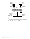
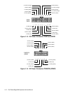
Figure 1-8. DC Power Connector J11 (P1)
13
W
RGOOD
2
(orange)
14 15 16 17 18 19 20 21 22
J11 (P1)
+5 VDC (red)
+5 VDC (red)
+5 VDC (red)
+5 VDC (red)
PSON#
1
(gray)
common (black)
common (black)
common (black)
–5 VDC (white)
+5 VDC (red)
23 24
+3.3 VDC (orange)
+3.3 VDC (orange)
12345 910
+5 VDC (red)
11 12
+3.3 VDC (orange)
+5 VDC sense (red)
6
7
8
common (black)
–sense (black)
+5 VFP (purple)
+12 VDC (yellow)
-12 VDC (blue)
common (black)
common (black)
+3.3 VDC sense (orange)