


14
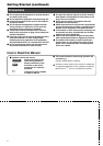
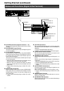
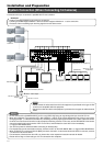
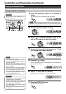
System Connection (When Connecting 16 Cameras)
Installation and Preparation
• Please consult the sales outlet from which this equipment is purchased on the type of UPS
units that are compatible with this equipment.
• Consult the outlet from which this equipment is purchased on the types of usable external
HDDs.
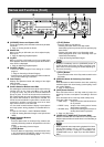
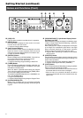
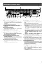
• Do not connect CCU’s [CAMERA INPUT] to VR-716’s [VIDEO IN]. Doing so may damage the input circuit of VR-716.
• When this equipment is connected to CCU, “NO VIDEO IN ** INPUT (E-03)” will be displayed on the screen if error occurs
during signal input. (** indicates the Camera No.) Recording cannot be properly performed in such a state at both the camera
for which error has occurred as well as at other properly functioning cameras. In this case, set the REC MODE of the camera
channel for which error has occurred to “OFF” on the menu, and eliminate the cause of the error immediately.
☞ Page 24 ‘REC MODE Menu’
•Turn OFF the power of all devices before connecting or disconnecting.
•For channels that are not connected to cameras, set them to “OFF” on the “REC MODE” Menu. ☞ Page 24 ‘REC MODE Menu’
• When [THRU OUT] is connected with the [BNC] connector, the built-in 75 ¸ terminal will be left OPEN. In this case, connect
a 75 ¸ terminal to the last device.
•For connection of devices other than VR-716, please refer to the respective instruction manuals for details.
• Please refer to Page 73 ‘Connecting to a PC’ for connection with computers.
Caution
Notes
Connection with up to 16 cameras is possible with VR-716’s switcher.
•Perform recording/playback by connecting to 16 cameras.
• Checking recorded images at Monitor 1 and live camera images on Monitors 2 ~ 5 at the same time.
•Execution of alarm recording upon receiving signals from the alarm sensor.
Camera 2
Camera 16
Control (Communication) Terminal
AC 220 V - 240 V
Output
Alarm Sensor
Monitor 5
Monitor 1
Monitor 2 Monitor 3
Monitor 4
Computer
External Hard Disk
Drive
Power Cord
(Supplied with this equipment)
AC 220 V - 240 V Output
<Example>
•••••••
COM
EXT REC
OUT
REC
SER
IN
OUT
RST
CLK
OUT
WAR
INCOMRST
OUT
161412108642
15131197531
ALARM
13 169 12
5
81 4/ 16
EE OUT
SCSI
RS-232C UPS
21
AUDIO OUT VIDEO OUT
21
LAN
AUDIO IN
VIDEO IN
THRU OUT
12345678910111213141516
CAUTION
RISK OF ELECTRIC SHOCK
DO NOT OPEN
AVIS:RISQUE DE CHOC
ELECTRIQ
[VIDEO IN]
[VIDEO IN]
[AUDIO IN]
UPS
[ALARM IN] [COM]
AC IN
(220V–240V )
SIGNAL GND
Camera 1
AC 220 V - 240 V
AC 220 V - 240 V
50 Hz/60 Hz