


70
Useful Features (continued)
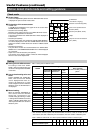
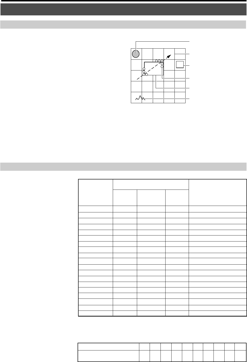
Motion detect check mode and setting guidance
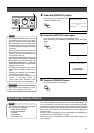
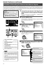
Check mode
ALARM mark
(Red: Alarm is ongoing)
Object
Frame of the specified area for
detection (White)
Detection point (White, Green)
Detection area boundary (Blue)
Graph of sum total for detection
point (Yellow)
Setting
Ⅵ Setting value for different scene
For setting to other than “STAN-
DARD”, refer to the setting value from
the arrow on the right side of “SCENE”
in the menu.
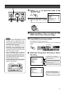
Ⅵ How to check setting value and
alarm
Perform “SCENE” and “AREA SET-
TING”, make sure that the ALARM
mark is displayed when there is a
motion to be detected as in check
mode. Change the scene or widen the
detection area if the ALARM mark is
not displayed.
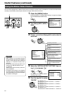
Ⅵ Manual setting
When the selected “STANDARD” or
other scenes cannot be detected,
change the 3 parameters in the
manual setting by referring to ‘Table
1: Setting value for different scene’ and
‘Table 2: “OBJECT SIZE LEVEL” and
“Alarm operation Minimum number of
detection point”’.
Table 1: Setting value for different scene
“SCENE”
Detailed setting
Alarm operation
Minimum number of detection
point *
1
“STANDARD”
“DOORWAY H”
“DOORWAY L”
“PASSAGE H”
“PASSAGE L”
“REGISTER H”
“REGISTER L”
“ATM H”
“ATM L”
“LOBBY H”
“LOBBY L”
“GATE H”
“GATE L”
“PARKING LOT H”
“PARKING LOT L”
“LOW LUX H”
“LOW LUX L”
“ELEVATOR”
“COUNTER”
2
2
4
2
4
1
4
1
20 *
2
2
4
1
8
1
10 *
2
2
6
2
6
“OBJECT SIZE LEVEL”
Alarm operation Minimum
number of detection point
Table 2: “OBJECT SIZE LEVEL” and “Alarm operation Minimum number of detection point”
12 3 45 678910
12 4 681015202530
*
1
Number of white dot displayed in check mode
*
2
The maximum number of point to be detected within one area is 9. Set the number of area
such that the sum total of detection point exceeds the minimum number of detection point.
“DETECTING
SENSITIVITY”
“TERMINATION
SENSITIVITY”
“OBJECT
SIZE
LEVEL”
–
10
7
9
8
10
10
10
8
10
7
14
10
14
10
15
12
8
6
–
+1
+4
+0
+3
+2
+2
+3
+5
+4
+8
+0
+4
+0
+4
+0
+0
+4
+5
–
2
3
2
3
1
3
1
8
2
3
1
5
1
6
2
4
2
4
Ⅵ Screen image
Press and hold [SEARCH] button when the “AREA SETTING” screen
is displayed to open the check mode screen.
Ⅵ Explanation of the screen content
• ALARM mark:
A red [a] will be displayed on the upper left of the screen when
ALARM detection is ongoing.
• Detection area boundary (Blue):
Boundary of the setting unit area in the “AREA SETTING” screen.
•Frame of the specified area for detection:
The area as specified in the “AREA SETTING” will be displayed as
a white frame.
• Detection point (White):
The point where motion has reached the “DETECTING SENSITIV-
ITY” will be displayed as a white dot. ALARM detection will be acti-
vated if the number of white dot hits the number of “OBJECT SIZE
LEVEL”.
• Detection point (Green):
The point where motion has reached between the “DETECTING
SENSITIVITY” and “TERMINATION SENSITIVITY” will be displayed
as a green dot.
•Graph of sum total for detection point (Yellow):
The changes in the display number of white dot will be displayed
with the x-axis as the elapsed time.