


9
COM
EXT REC
OUT
REC
SER
IN
OUT
RST
CLK
OUT
WAR
INCOMRST
OUT
161412108642
15131197531
ALARM
13 169 12
5
81 4/ 16
EE OUT
AC IN
SCSI
RS-232C UPS
21
AUDIO OUT VIDEO OUT
21
LAN
AUDIO IN
VIDEO IN
THRU OUT
12345678910111213141516
SIGNAL GND
CAUTION
RISK OF ELECTRIC SHOCK
DO NOT OPEN
AVIS:RISQUE DE CHOC
ELECTRIQ
(220V–240V )
)¤ ⁄
‹ fi fl ‡› ° ‚· ¡
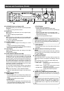
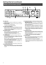
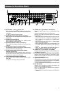
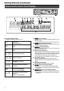
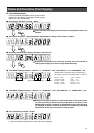
Names and Functions (Rear)
) [AC IN (220 V - 240 V )] Power Inlet
Connect using the power cord supplied to an AC 220 V -
240 V outlet. The main unit will turn on automatically when
connected.
☞ Page 15 ‘Turning On/Off the Power’
⁄ [VIDEO IN] Camera Image Signal Input (BNC)
Connect this to the video output of the video camera (sold
separately).
¤ [AUDIO IN] Terminal (RCA)
Connect this to the audio output of the device for which
audio recording is to be performed.
‹ [RS-232C] Remote Terminal (D-sub 9 Pin)
VR-716 can be controlled externally by connecting it to a
computer.
› [SCSI] Terminal (68-pin Ultra Wide SCSI)
For connection to external hard disk drive (sold separately)
and DVD-RAM drive (sold separately).
fi [UPS] Uninterruptible Power Supply Control
Terminal (D-sub 9 Pin)
For connection to the communication control connector of
the UPS unit. For more details, please consult the outlet
from which this equipment is purchased.
fl [LAN] Connection Interface (100 Base-T)
For connection to the Intranet and other networks using a
LAN cable.
☞ Page 76 ‘Connecting Using a LAN Cable’
‡ [AUDIO OUT 1, 2] Terminals 1 and 2 (RCA)
Outputs the audio input when in the Recording or Stop
mode.
Outputs recorded audio when in the Play mode.
However, there will be no audio output in the following
circumstances:
• When playing back recorded images for which the frame
rate is set as “1/6 IPS” (1 image per 6 seconds) or “1/12
IPS” (1 image per 12 seconds) in the “FRAME RATE”
menu switch.
• When performing search other than x 1 mode or during
Still or single frame playback.
• When playing back images with the “AUDIO REC” item
in the “REC MODE” menu selected as “OFF” during re-
cording.
•When the “MAIN MENU/OPERATION MENU” or
“SEARCH MENU” is displayed in the Play mode.
° [VIDEO OUT 1, 2] Terminals 1 and 2 (BNC)
Outputs images selected using the Camera Selection But-
tons 6 on the front panel.
· [THRU OUT] Camera Image Output Terminal (BNC)
Outputs camera image signals that correspond to each
[VIDEO IN] terminal ⁄. For connection to TV monitors.
(Automatic termination)
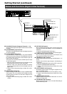
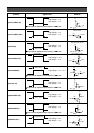
‚ Signal Input/Output Terminal
For operating VR-716 using external alarm/sensor signals
or signals received from external devices, or for operating
external devices by outputting signals.
☞ Page 10 ‘Names and Functions (Signal In/Out Terminal)’
¡ [EE OUT] (BNC)
Outputs the live images on cameras connected to the
[VIDEO IN] terminals ⁄ in quad picture.
The [1-4 / -16] connector can also be used to output im-
ages in 16 split pictures.
☞ Page 32 ‘When Connecting the Monitor to the [EE OUT]
terminal’