


26
Menus (continued)
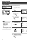
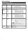
“MONITOR DISPLAY” Menu
Item Settings Description
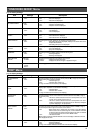
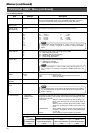
“EE OUT1 - 4/ -16”
“SINGLE PICTURE
MODE”
“SINGLE PICTURE
MODE”
“CAMERA1”
~ “CAMERA16”
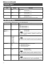
“QUAD PICTURE
MODE”
“BLOCK 1”
~ “BLOCK 4”
“ALARM/SENSOR
SWITCH”
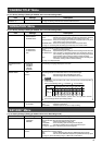
“SPLIT SCREEN
BORDER COLOR”
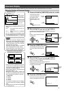
For setting the screen during output of camera images in VR-716 to the [EE OUT
1-4/-16] terminal.
“1-4” :Images displayed in quad picture.
“1-16” : Images displayed in 16 split pictures.
☞ Page 32 ‘When Connecting the Monitor to the [EE OUT] terminal’
For setting the time interval at which display at VR-716 is switched from the live
image of one camera to another.
“OFF” : Automatic switching of camera channels turned off.
“1 SEC” :Switches camera channel at an interval of 1 second.
“2 SEC” :Switches camera channel at an interval of 2 seconds.
“3 SEC” :Switches camera channel at an interval of 3 seconds.
“4 SEC” :Switches camera channel at an interval of 4 seconds.
“5 SEC” :Switches camera channel at an interval of 5 seconds.
“10 SEC” : Switches camera channel at an interval of 10 seconds.
☞ Page 34 ‘Setting Time Interval for Switching Displays in the Single Picture Mode’
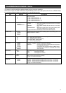
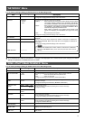
For setting the time interval at which display is switched from one camera channel
block to another when in quad picture.
“OFF” : Automatic switching of camera channels turned off.
“1 SEC” :Switches camera channel at an interval of 1 second.
“2 SEC” :Switches camera channel at an interval of 2 seconds.
“3 SEC” :Switches camera channel at an interval of 3 seconds.
“4 SEC” :Switches camera channel at an interval of 4 seconds.
“5 SEC” :Switches camera channel at an interval of 5 seconds.
“10 SEC” : Switches camera channel at an interval of 10 seconds.
☞ Page 35 ‘Setting Time Interval for Switching Displays in the Quad Picture Mode’
For setting the switching mode of the monitor screen when alarm/sensor signals are
received.
“OFF” : Sends output to monitor according to the Camera Selection button
settings.
“SEQUENTIAL” :Sends only output of cameras for which alarm has been triggered
to the monitor in sequence. (Switching of display is fixed at an inter-
val of 1 second.)
“FIX” : Sends only output of the camera for which its alarm has last been
triggered to the monitor.
For setting the brightness of the border line of split screen.
“BORDER 1” : Dark grey
“BORDER 2” : Grey
“BORDER 3” : Bright grey
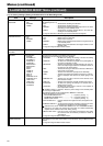
● “1-4”
“1-16”
“OFF”
● “1 SEC”
“2 SEC”
“3 SEC”
“4 SEC”
“5 SEC”
“10 SEC”
“OFF”
● “1 SEC”
“2 SEC”
“3 SEC”
“4 SEC”
“5 SEC”
“10 SEC”
● “OFF”
“SEQUENTIAL”
“FIX”
“OFF”
“BORDER 1”
“BORDER 2”
● “BORDER 3”
[ ● ] are factory settings.
• Screen display of monitor can be switched using the Camera Selection but-
tons even when “SEQUENTIAL” or “FIX” are selected.
• When multiple alarms are simultaneously detected, image of cameras for which
alarm has been triggered will be output to the monitor alternately even when
“FIX” is selected.
Notes