


18
•••••••••••••••••••••••••••••••••••••••••••••••••••••••••••••••••••••••••••••••••••••••••••••••••••••••••••••••••••••••••••••••••••••••••••
•
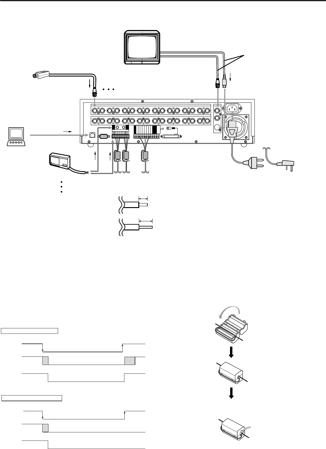
Connections
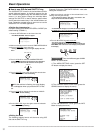
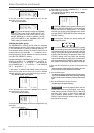
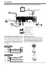
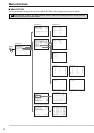
■ Connecting to CCTV camera, monitor, sensor, the electric power supply and ferrite core
MONITOR
To
VIDEO OUT
or
S(Y/C) OUT
terminal
One of either codes should
be connected.
To CAMERA IN 1
terminal
CAMERA #1
To S(Y/C) IN
terminal
To GND
terminal
To ALARM IN terminal
corresponds to the
CAMERA #.
Up to 16 cameras
12345678910111213141516
CAMERA IN
12345678910111213141516
CAMERA OUT
VIDEO OUT
Y/C
CLOCK ADJ
REC
POWER ON
POWER OFF
ALARM OUT
MODE OUT
CALL OUT
CALL OUT GND
GND
GND
DC 5V OUT
MAX 30mA
GND
RS-232C
ETHERNET
RESET
ON
SCSI
SCSI
TERMINATION
GNDGND
16
15
14
13
12
11
10
9
8
7
6
5
4
3
2
1
ALARM IN
OFF
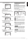
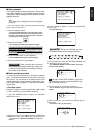
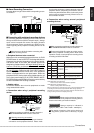
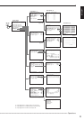
Processing the connecting line
Connection on the ALARM IN side
Compatible power lines
ø0.32 ~ ø0.65 mm (AWG 28 ~ 22)
Connection on the I / O side
Compatible power lines
ø0.4 ~ ø1.2 mm (AWG 26 ~ 16)
Cut the designated area from the electric
wire’s outer covering (vinyl portion).
10~12mm
5~7mm
To ETHERNET
Socket
POWER CORD
for U.Kfor the Continent
Ferrite core
SENSOR #1
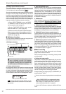
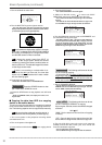
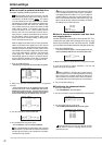
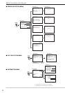
■ Turning ON/OFF this Unit by peripheral source
By using POWER ON/POWER OFF terminal on (I/O termi-
nals) , it is possible to turn on/off this unit externally. This
function is related to the output of DC 5V OUT terminal.
The relationship between POWER ON/POWER OFF termi-
nal, DC 5V OUT terminal and turning on/off this unit is shown
in the diagram. Please use suitable peripheral devices to con-
nect with this unit.
Using POWER ON terminal
POWER ON
terminal
ground
0V
power off
Unit's
power
DC 5V OUT
(4.5-5.5V
Max.30mA)
DC 5V
power on
power on
shut down
boot
up
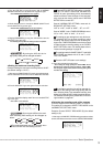
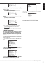
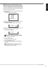
Using POWER OFF terminal
POWER OFF
terminal
0V
power off
ground
shut down
power on
Unit's
power
DC 5V OUT
(4.5-5.5V
Max.30mA)
DC 5V
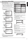
■ Attaching the ferrite core
To avoid interference from the cables connected to the unit
against other apparatus, attach the ferrite core to all ca-
bles connected to the control terminal cables and ALARM
IN terminals (GND terminals) as indicated and place it as
close to the unit as possible. Use the ferrite core to bundle
together all of the cables connected to each terminal.
Tie cables at the band
To the other apparatus