


19
•
••••••••••••••••••••••••••••••••••••••••••••••••••••••••••••••••••••••••••••••••••••••••••••••••••••••••••••••••••••••••••
Connections
ENGLISH
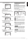
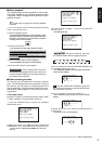
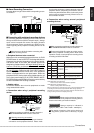
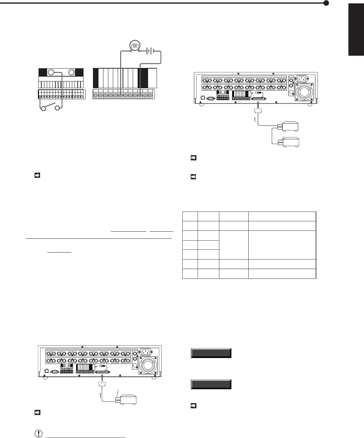
■ Alarm Recording Connection
Example: When using the alarm switch corresponding to cam-
era number 1.
ALARM IN
GND GND
CLOCK ADJ
REC
POWER ON
POWER OFF
ALARM OUT
MODE OUT
CALL OUT
CALL OUT GND
DC 5V OUT
MAX 30mA
alarm switch
peripheral alarm lamp
or buzzer
GND
GND
GND
16
15
14
13
12
11
10
9
8
7
6
5
4
3
2
1
■ Connecting with peripheral recording devices
By connecting peripheral recording devices to the main unit
through its SCSI interface (SCSI-II half-pitch 50-pin), storage
space can be increased and archive and copying functions
can be performed. Please consult with your retailer for infor-
mation regarding which peripheral recording devices can be
used.
Make sure to turn off this Unit when connecting with
peripheral recording devices.
♦ Peripheral devices to be connected
When the unit is connected to peripheral devices, its PLAY
DEVICE button is used to SELECT the designated device.
Response may be slow depending on the type of periph-
eral device used. In this case, the indicator light on the
designating playback device will begin flashing; other op-
erations cannot be performed when in this condition.
Resume operation only after the playback device’s indica-
tor light illuminate. Please use the unit’s EJECT button to
eject the peripheral device media even if the peripheral
device is equipped with its own eject button. When the
peripheral device is being used as the playback device, all
of the front panel buttons (PLAY, STOP, PAUSE, MULTI-
PLEXER functions and ZOOM) will function normal as they
do when the MAIN HDD is being accessed.
♦ Usable cables
Connections between the unit and its peripherals are made
using standard SCSI cables.
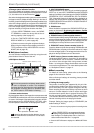
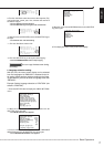
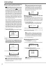
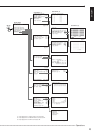
♦ Connection when using 1 peripheral recording
device
SCSI
12345678910111213141516
CAMERA IN
12345678910111213141516
CAMERA OUT
VIDEO OUT
Y/C
CLOCK ADJ
REC
POWER ON
POWER OFF
ALARM OUT
MODE OUT
CALL OUT
CALL OUT GND
GND
GND
DC 5V OUT
MAX 30mA
GND
RS-232C
ETHERNET
RESET
ON
SCSI
TERMINATION
GNDGND
16
15
14
13
12
11
10
9
8
7
6
5
4
3
2
1
ALARM IN
OFF
SCSI cable
Peripheral
recording
device
Terminator
SCSI
terminal
When connecting a peripheral recording device, the
SCSI TERMINATION switch must be set to OFF.
Warning concerning connections
A terminator is necessary to maintain proper electrical
connections to the peripheral devices. Please make
sure that the terminator is always attached to the last
peripheral device. (Depending on the device, the ter-
minator may be built into the device. In this case, please
set the built-in terminator correctly.) Please use an ac-
tive terminator for SCSI.
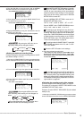
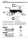
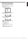
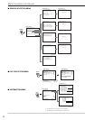
♦ Connection when using several peripheral
recording devices
SCSI
12345678910111213141516
CAMERA IN
12345678910111213141516
CAMERA OUT
VIDEO OUT
Y/C
CLOCK ADJ
REC
POWER ON
POWER OFF
ALARM OUT
MODE OUT
CALL OUT
CALL OUT GND
GND
GND
DC 5V OUT
MAX 30mA
GND
RS-232C
ETHERNET
RESET
ON
SCSI
TERMINATION
GNDGND
16
15
14
13
12
11
10
9
8
7
6
5
4
3
2
1
ALARM IN
SCSI cable
SCSI cable
Peripheral
recording
device
Terminator
SCSI cable
SCSI
terminal
OFF
When connecting a peripheral recording device, the
SCSI TERMINATION switch must be set to OFF.
Please set the SCSI ID number to suit the use/pur-
pose of the peripheral recording device. Refer to the
operation manual of each peripheral recording device
for setting its SCSI ID Number.
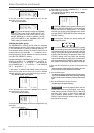
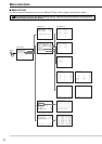
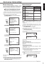
Connected
device
Maximum recording capacity is 103GB
per unit.
0
1
2
3
4
5
Notes
SCSI ID
Number
Built-in HDD
HDD
HDD
HDD
DDS/RDD
DDS/RDD
HDD expansion/
HDD recording
Archive
Copy
Purpose
Recording
Will be recognized as an archive device.
Will be recognized as a copy device.
* RDD: Abbreviation of removable disk drive.
Select a disk drive which can eject the recording medium.
* HDD: Abbreviation of hard disk drives.
Please use those which include self-defect capabilities.
* DDS: Abbreviation of digital data storage.
Select a recording medium which uses tape.
* When hard disk drives are connected to ID1, ID2, or ID3, the displayed estimates
of recording time will include the expanded HDD. When storage capacity is
expanded to its maximum, however, there will be instances where the times set
for long recording intervals are not displayed correctly.
INFORMATION
Please use the devices we have rec-
ommended for this unit’s peripheral recording devices.
Please consult with your dealer for details.
INFORMATION
Storage capacity is indicated in
gigabytes (GB). (1GB = 1000 x 1000 x 1000 bytes.)
For details of functions of the archive device and
the copy device, please refer to “Glossary” on page
83.