


66
•••••••••••••••••••••••••••••••••••••••••••••••••••••••••••••••••••••••••••••••••••••••••••••••••••••••••••••••••••••••••••••••••••••••••••
•
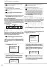
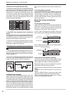
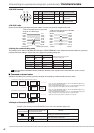
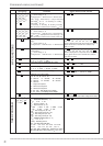
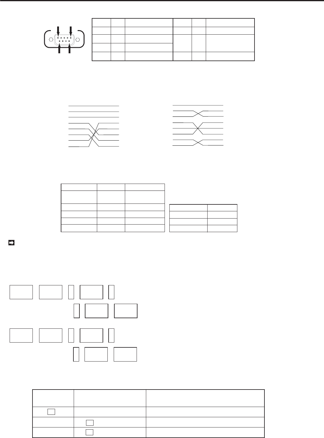
♦ RS-232C terminal
RS-232C
1
6
9
5
2
3
4
5
RXD
TXD
DTR
GND
Receiving Data
Transmission Data
Data Terminal Ready
Signal Ground
Pin NO.
Letters Letters
Pin NO.
Transmition Contents Transmition Contents
6
7
8
DSR
RTS
CTS
Data Set Ready
Transmission
Requirement
Transmission Clear
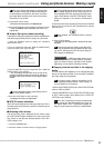
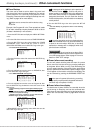
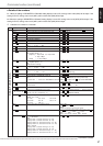
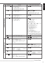
♦ RS-232C cable
Please use the following RS-232C Crossover cable to connect your personal computer to the Unit.
FRAME
D-SUB 9 pin (unit) D-SUB 25 pin(Personal computer)
FG
TXD
RXD
RTS
CTS
DSR
GND
DTR
1
2
3
4
5
6
7
20
RXD
TXD
DTR
GND
DSR
RTS
CTS
2
3
4
5
6
7
8
1) When RS-232C terminal of personal
computer is D-SUB 25 pin
D-SUB 9 pin D-SUB 9 pin
FRAMEFRAME
RXD
TXD
DTR
GND
DSR
RTS
CTS
2
3
4
5
6
7
8
RXD
TXD
DTR
GND
DSR
RTS
CTS
2
3
4
5
6
7
8
2) When Pesonal cpmputers RS-232C
terminal is D-SUB 9 pin
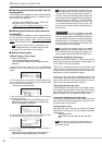
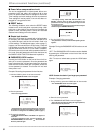
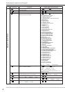
♦ Setting the communicating mode
The settings can be made on RS-232C SETTING of the <REAR TERMINAL> menu. Set the Unit and the modem or a personal
computer with same settings. Please refer to the diagram for possible setting rate.
1
2
3
4
5
TRANSMISSION
RATE
DATA BIT LENGTH
PARITY BIT
STOP BIT
DELIMITER
1200/2400/4800/
9600
8 BIT/7 BIT
NONE/ODD/EVEN
1 BIT/2 BIT
CR/CR•LF
Synchronization Name on Menu
Asynchronous
1
2
3
X control
S parameter
CS-RS hamd-shake
Not available
Not available
Available
Synchronization Name on Menu
# Set other functions on the personal
computer as shown below.
Transmission rate at
the data received/
sent
Data bit length
Parity bit setting
Stop bit length
Line feed setting
Please note that the RS-232C interface (located on the back of the unit) does not function while the unit is in commu-
nication mode.
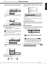
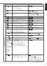
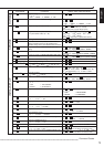
■ Command code and status
Operation and setting of this unit by a personal computer is executed by command codes and error codes.
Delimeter
(sending) #1
Delimeter
(receiving) #2
Parameter 1
Parameter n
Command code
Status
Parameter 2
Parameter 1
Parameter n
Parameter 2
, ,
,
• • • • • • • • • •
• • • • • • • • • •
• • • • • • • • • •
• • • • • • • • • •
1) Command : an order from a personal computer to the unit
2) Command : a reply from the unit ( indicated on a personal computer)
, ,
,
#1: If you set the DELIMITER setting to "CR" on the RS-232C setting menu,
input a Carrige return code (0DH).
If you set the DELIMITER setting to "CR • LF" on the RS-232C setting menu,
input a carrige return code (0DH) and a line
****
code (0AH).
#2: If you set the DELIMITER setting to "CR" on the RS-232C setting menu,
output a Carrige return code (0DH).
If you set the DELIMITER setting to "CR • LF" on the RS-232C setting menu,
output a carrige return code (0DH) and a line
****
code (0AH).
Make sure to send commands in an interval of 0.1 second.
♦ Example of Command operation
PW1
CR
RC
EX
CR
CR
Example 1) Turn the Unit on.( when DELIMITER is set to "CR" on the RS-232C setting menu)
Command from
personal computer
Replied status code from uint
to a personal computer
Meaning
Sending a command to turn the Unit on.
The unit received a command and executed.
The unit received a command.
Connecting to a personal computer
Command code
Connecting to a personal computer (continued)
/ Command codes