


108
It is necessary to adjust communication speed and use the
same communication protocol with external devices such
as a controller when connecting those external devices to
the DATA port or the SERIAL port (RS232C).
It is also required to perform the settings for the network
such as the IP address and the gateway address when
operating this unit a PC via a network such as LAN.
These are the descriptions of how to perform the required
settings for communication with external devices.
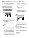
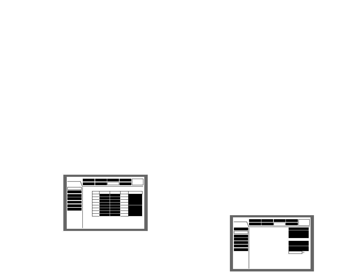
q [Camera Control] Settings of the
communication method and the
cable compensation for camera
control
Select a communication method for each camera chan-
nel to control cameras from the following.
Coaxial: Controls camera with the coaxial communica-
tion (CAM 1 - 8 CH are available for WJ-HD316,
CAM 1 - 6 CH are available for WJ-HD309)
PSD: Controls camera with the PS·Data. (CAM 9 - 16
CH are available for WJ-HD316, CAM 7 - 9 CH are
available for WJ-HD309)
RS 485: Controls camera with the RS 485 communica-
tion. (CAM 1 - 16 CH are available for WJ-HD316,
CAM 1 - 9 CH are available for WJ-HD309)
OFF: Does not control camera (CAM 1 - 16 CH are
available)
Notes:
• Perform settings according to the cameras connect-
ed to this unit.
• CAM 9-16 control 4 cameras each (only for
WJHD316).
• When using the coaxial communication to control
cameras, connect cameras to the VIDEO IN con-
nectors 1 - 8 for WJ-HD316 (1 - 6 for WJ-HD309)
(coaxial communication compatible). When control-
ling cameras connected to other VIDEO IN connec-
tors with coaxial communication, use a coaxial com-
munication unit (WJ-MP204). In this case, select
"PSD" for the communication method for the camera
channels to be controlled through the axial commu-
nication unit.
• To prevent operation mistake, set to OFF for the
unused camera channels.
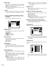
It is possible to compensate the video signal trans-
mission loss from the camera when using the
VIDEO IN connector 1 - 8. (cable compensation)
Perform the setting for the cable compensation
according to the used cable length.
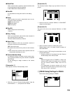
S: When the used cable length is shorter than 500
m
M: When the used cable length longer than 500 m
and shorter than 900 m
L: When the used cable length longer than 900 m
and shorter than 1 200 m
Notes:
• Use 5C-2V cables for the cable compensation.
• Perform the setting for the cable compensation
properly according to the cable length. Otherwise
camera pictures may not be displayed/recorded
correctly.
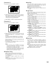
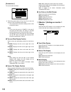
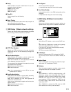
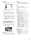
w [PS Data Setup] Settings for the
PS·Data
Perform the following settings for the PS·Data.
● Unit Address (System)
A unit address (System) is a unique number assigning
to PS·Data devices. The addresses must be unique to
identify system devices when connecting multiple
devices compatible with PS·Data. Numbers, "001"-"099",
are to be assigned as the unit addresses to the system
devices.
● Unit Address (Controller)
The unit address (controller) is used to control a
PS•Data device connected to this unit. Numbers, "001"
- "099" are to be assigned.
● Cascade
Select ON or OFF whether or not to use the cascade
connection.
Set this to ON when connecting two units or more in the
cascade connection.
ON: Select this when connect units in the cascade con-
nection.
OFF: Does not function.
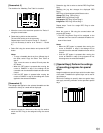
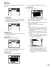
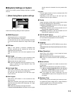
■ [Communication] Settings for communications with other devices
Schedule
System
Com
Switcher
SETUP MENU
LIVE
Maintenance Recording Event
Display
Camera Control
PS.Data Setup
RS485 Setup
RS232C Setup
NW Setup 1
NW Setup 2
NTP Setup
■
Type of Camera Control
CAM1
CAM2
CAM3
CAM4
CAM5
CAM6
CAM7
CAM8
CAM9
CAM10
CAM11
CAM12
CAM13
CAM14
CAM15
CAM16
RS485
PSD
S
S
S
S
S
S
S
S
COAX
COAX
COAX
COAX
COAX
COAX
COAX
COAX
CAM CAM TYPECOMP TYPE
Schedule
System
Com
Switcher
SETUP MENU
LIVE
Maintenance Recording Event
Display
Camera Control
PS.DATA Setup
RS485 Setup
RS232C Setup
NW Setup 1
NW Setup 2
NTP Setup
SETUP
001
001
1s
OFF
1
NONE
8
9600
OFF
■
Unit Adress(System)
■
Unit Adress(Controller)
■
Cascade
■
Baud Rate
■
Data Bit
■
Parity
■
Stop Bit
■
Retry Timing
■
Alarm Data
■
Camera Number Setup