


11
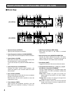
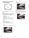
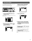
!1 PS·Data Ports (DATA)
Connect PS·Data compatible devices with these ports.
!2 Mode Switches (MODE)
Set the operation mode of this unit with these dip
switches.
!3 RS485 Ports (RS485 (CAMERA))
Connect RS485 compatible combination cameras with
these ports.
!4 Network Port (10/100BASE-T)
Connect this unit to a network compatible with 10BASE-
T or 100BASE-Tx when controlling this unit using a PC
via network.
!5 Copy Port (COPY1)
Connect a recommended DVD-RAM drive, CD-R drive
or DVD-R drive with this port.
!6 Extra Storage Port (EXT STORAGE)
Connect an optional extension unit (WJ-HDE300) with
this port.
!7 Power Switch (POWER)
Turns the power of this unit on and off.
!8 Signal Ground Terminal (SIGNAL GND)
!9 Power Cord Inlet (AC IN)
Connect the power cord to this inlet.
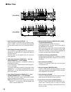
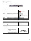
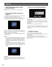
■ On the Monitor 1 (To display
only live image)
1. Camera Title
Displays the edited camera title.
A position to display a camera title can be selected
from the following.
Upper left, upper right, lower left, lower right, center
The default camera title position is lower right (R-
LOWER).
2. Time
Displays the current time (hour:minute:second) and
date (year:month:day).
A position to display the time can be selected from the
following.
Center, upper left, lower left, upper right, lower right
The default time display position is lower left (L-
LOWER).
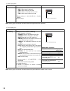
Note: When the camera title and the time display are
layered in a multi-screen display, only the time dis-
play will be displayed.
3. Alarm Display
When an alarm occurred, an alarm display will be dis-
played.
The alarm display will be displayed differently as fol-
lows depending on which alarm has occurred.
VMD-*: When motion is detected.
LOSS-*: When video loss occurred.
COM-#: When a command alarm occurred.
TRM-#: When a terminal alarm occurred.
*: Camera number (1 - 16 for WJ-HD316, 1 - 9 for WJ-
HD309)
#: Event number
Note: Refer to page XX for further information about
event types and event actions.
q
q
q
q
q
wewe
wewe