


76
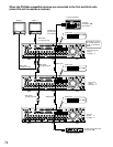
■ How to Use the Alarm/Control Terminals
These terminals are used for emergency recording, auto time adjustment (Auto Adjust Time), taking measures against power
outages (Shutdown Time), and when installing a buzzer, a lamp, and such an alarming device. They are also used to synchro-
nize with the sequential display changeover.
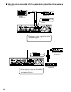
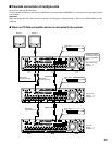
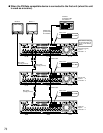
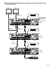
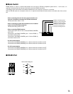
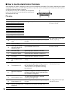
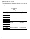
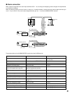
The terminal pin array and connections are exemplified
below. The connector to be used should be manufactured
according to the pin array.
Pin array
Pin No.
1
Pin No.
Ch 8 alarm output
Operation
Alarm signal output at an event occurrence Open collector output
24 V max., 100 mA
Starting emergency recording disk space a sig-
nal input
Generation of signal output for disk space alarm-
ing of DVD-RAM, DVD-R, CD-R
Open collector output
24 V max., 100 mA
Remarks
2 Ch 9 alarm output
3 Ch 10 alarm output
4 Ch 11 alarm output
5 Ch 12 alarm output
6 Ch 13 alarm output
7 Ch 14 alarm output
8 Ch 15 alarm output
9 Ch 16 alarm output
10 NC
11 Alarm display reset input
12
Emergency recording
input
13, 14 Earth (Grounding)
15
Alarm output for available
disk space of device con-
nected to copy port
Signal output upon detection of HDD error
16 HDD error output
Signal output upon detection of camera error
17 Camera error output
Signal output upon detection of unit error
18 Error output
Signal output upon completion of outage pro-
cessing
High (+12V)
19
End of outage process-
ing
Time of this unit is adjusted to the preset time
according to the signal input. This signal output is
then generated for the setting time of this unit.
Time of all other units is adjusted to the setting
time of this unit.
30 kΩ 5 V pull-up,
–100mA/make contact
20 Time adjustment I/O
Sequence changeover is effected according to
the signal input. Signal output is generated at the
time of sequence changeover.
21
Sequence changeover
I/O
The state of alarm suspension is assumed
according to the signal input.
22 Alarm suspension input
Start of outage processing according to the sig-
nal input.
Non-voltage make contact input
–100 mA/5 V pull-up
23 Outage detection I/O
Changeover to the external recording mode
24
External recording mode
changeover
Canceling the alarm display
Non-voltage make contact input
–100 mA, 5 V pull-up
25 +5V output +5V output 200 mA max.
q!3
@5 !4
ALARM/CONTOROL