


69
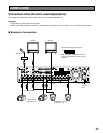
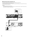
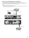
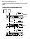
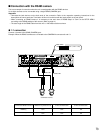
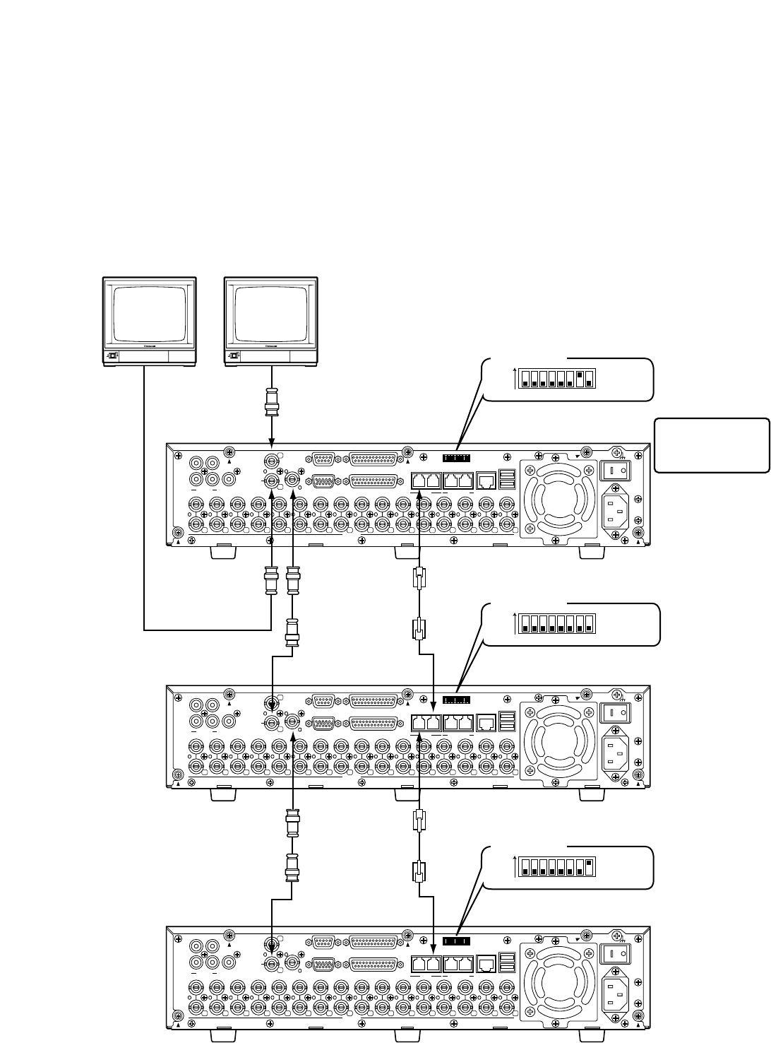
■ Cascade connection of multiple units
Up to of four units can be connected.
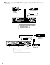
For the cascade connection, connect the CASCADE IN connector and the CASCADE OUT connector on the rear panel of each
unit as below.
Important:
When connecting the unit in the cascade connection, set "Cascade" of "PS·Data Setup" in "Com" on the SETUP MENU to "ON".
(Page xx)
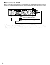
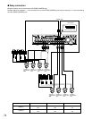
● When no PS·Data compatible device is connected to the system
Monitor 1
First unit (this unit)
System : 1
Controller : 1
Second unit
System : 2
Controller : 2
Third unit
System : 3
Controller : 3
Monitor 2
Mode switch
(No. 7: ON)
67812345
ON
Mode switch
(No. 8: OFF)
67812345
ON
Mode switch
(No. 8: ON)
67812345
ON
12
IN
OUT
CASCADE
OUT
16
16
3
15
15
14
14
13
2
1
13
12
12
11
11
10
10
9
9
8
8
7
7
6
6
5
5
4
4
3
3
2
2
1
1
VIDEO
AUDIO IN AUDIO OUT
MONITOR OUT CASCADE IN
MONITOR (VGA) ALARM/CONTOROL
SERIAL ALARM
POWER
COPY 1
MODE
EXT STORAGE10/100BASE-TRS485(CAMERA)
D ATA
AC IN
SIGNAL GND
1
4 2
12
IN
OUT
CASCADE
OUT
16
16
3
15
15
14
14
13
2
1
13
12
12
11
11
10
10
9
9
8
8
7
7
6
6
5
5
4
4
3
3
2
2
1
1
VIDEO
AUDIO IN AUDIO OUT
MONITOR OUT CASCADE IN
MONITOR (VGA) ALARM/CONTOROL
SERIAL ALARM
POWER
COPY 1
MODE
EXT STORAGE10/100BASE-TRS485(CAMERA)
D ATA
AC IN
SIGNAL GND
1
4 2
12
IN
OUT
CASCADE
OUT
16
16
3
15
15
14
14
13
2
1
13
12
12
11
11
10
10
9
9
8
8
7
7
6
6
5
5
4
4
3
3
2
2
1
1
VIDEO
AUDIO IN AUDIO OUT
MONITOR OUT CASCADE IN
MONITOR (VGA) ALARM/CONTOROL
SERIAL ALARM
POWER
COPY 1
MODE
EXT STORAGE10/100BASE-TRS485(CAMERA)
D ATA
AC IN
SIGNAL GND
1
4 2
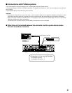
Unit Address settings
of "PS·Data Setup" of
"Com" on the SETUP
MENU
RS485 Cable
BNC Cable
(Locally procured)
BNC Cable
(Locally procured)
BNC Cable
(Locally procured)
RS485 Cable