


13
A/C-7P RO, A/C-7S RO
3. Installation
4.If the sharing port of the A/C-7P
RO is used, attach the parallel
cable now. Note that a PC or
LAN connected to the A/C-7P
RO’s sharing port should always
be powered up when the A/C-7P
RO is operating.
5.Connect the wall mount
transformer from the outlet to
the A/C-7P RO’s “9V”
connector. Connect the power
cord(s) to the printer and PC (if
used).
6.Power on the A/C-7P RO, then
printer. The A/C-7P RO’s green
LED lights labeled “Power” and
“Printer On Line” should be lit.
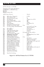
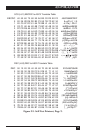
7.Print an A/C-7P RO self-test.
Power off the A/C-7P RO. Set
configuration switch SW1:8 (far
right) to the “|” position. Power
on the A/C-7P RO. After the
self-test prints, set configuration
switch SW1:8 back to the “o”
position, then cycle the power
one more time.
8. Refer to the self-test printouts
to determine which
configuration parameters need
to be altered. Change these
parameters by using the
Host/PC download commands.
9.With the A/C-7P RO powered
off, attach the coax cable from
the host to the A/C-7P RO’s
BNC connector.
Before connecting the A/C-7 RO to
the printer, verify that the printer
functions properly by performing a
printer self-test. Consult the printer’s
user’s guide for instructions on how
to start and evaluate the self-test. If
the printer functions properly,
proceed with the installation of the
A/C-7 RO.
WARNING
Electrical current from power
lines and cables connecting
the A/C-7 RO, printer, and PC
can be hazardous. To
minimize the danger, follow
the instructions below.
NOTE
Do not connect the interface
to the coax cable until Step
9.
To install the A/C-7P RO:
1.Power off the printer and PC (if
used) and disconnect the power
cord(s).
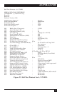
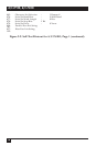
2.Use the configuration switches
located on the A/C-7P RO’s
front panel to select the desired
output protocol. Refer to Table
4.1 for configuration switch
settings.
3.Connect the parallel cable from
the interface’s “Parallel Out”
connector to the printer’s
parallel port.