


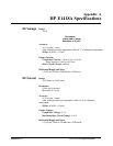
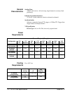
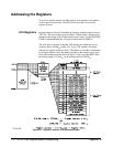
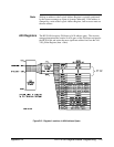
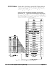
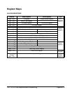
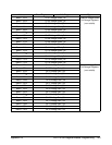
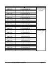
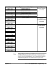
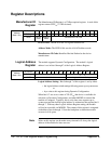

Reset and Registers
Following power-on or a *RST command, the registers are put into the
following states:
– The Manufacturer ID and Device ID Registers remain unaffected.
– The Channel Mode Register (base + 1A
16
) is set to voltage output
for all channels (FFFF
16
) or is set to the state set by the V/I jumper
(described on page 31) if the P/J jumper is in the jumper selectable
position.
– The Channel Program Jumper Register (base + 16
16
) is set to program
selectable for all channels (FFFF
16
) or to the position of the P/J jumper
(described on page 31).
– The Channel Relay Control Register (base + 1C
16
) is set to open all
channel relays (FFFF
16
).
– The Isolation Status Register (base + 14
16
) reflects the isolated/
non-isolated configuration of each channel.
– The Calibration Control Register (base +08
16
) is set to calibrate
voltage with the cal mux disabled (2000
16
).
– Channel Trigger Register (base + 18
16
) is set to 0000
16
if the
module is a 16-channel configuration or FF00
16
if an 8-channel
configuration.
Note The upper 8-bits of all channel related registers are set to 1’s (FF
16
) for
8-channel configurations.
Appendix B HP E1418A Register-Based Programming 119