


Chapter 1
Module Setup and Installation
Using This Chapter
This chapter provides general module information and tasks you must
perform to install and prepare your module. A procedure to verify your
installation is also given. The chapter is divided into the following sections:
• Module Description . . . . . . . . . . . . . . . . . . . . . . . . . . . . . . . . Page 13
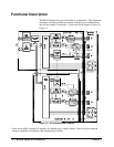
• Functional Description. . . . . . . . . . . . . . . . . . . . . . . . . . . . . . Page 16
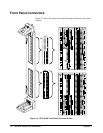
• Front Panel Connectors . . . . . . . . . . . . . . . . . . . . . . . . . . . . . Page 18
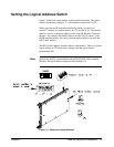
• Setting the Logical Address Switch. . . . . . . . . . . . . . . . . . . . Page 19
• Module Installation . . . . . . . . . . . . . . . . . . . . . . . . . . . . . . . . Page 20
• Terminal Modules . . . . . . . . . . . . . . . . . . . . . . . . . . . . . . . . . Page 22
• Wiring the Terminal Module . . . . . . . . . . . . . . . . . . . . . . . . . Page 23
• Attaching the Terminal Module. . . . . . . . . . . . . . . . . . . . . . . Page 25
• Removing the Terminal Module . . . . . . . . . . . . . . . . . . . . . . Page 26
• Terminal Module Options . . . . . . . . . . . . . . . . . . . . . . . . . . . Page 27
• Terminal Module Connectors . . . . . . . . . . . . . . . . . . . . . . . . Page 30
• Configuring the Terminal Module. . . . . . . . . . . . . . . . . . . . . Page 31
• Terminal Module Connections . . . . . . . . . . . . . . . . . . . . . . . Page 33
• Initial Operation . . . . . . . . . . . . . . . . . . . . . . . . . . . . . . . . . . . Page 37
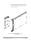
Module Description
The HP E1418A is an 8 or 16 channel digital-to-analog converter module
for use in a VXIbus C-size mainframe. The module is a register-based
device. The module can be programmed via direct register access or, with
the appropriate driver, by high level commands. This manual describes
programming the module using SCPI (Standard Commands for
Programmable Instruments) and the SCPI driver.
Each HP E1418A module is a unique instrument having its own output
buffer and error queue. Multiple modules cannot be combined into a single
instrument.
Each channel can be configured to either voltage or current output mode.
When configured for voltage output, voltages in the range of -16.0 to
+16.0 Volts can be set. When configured for current output, current in the
range of -0.02 to + 0.02 Amps can be set. The channel output mode can be
programmatically set, or, can be forced to either voltage or current by
mechanical jumpers on the terminal module.
Chapter 1 Module Setup and Installation 13