


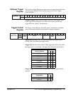
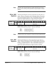
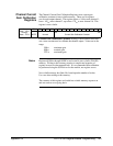

Note The Main_DAC Triggered Registers, together with the Trigger Control
Register, can be used to provide synchronized output changes on multiple
channels.
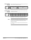
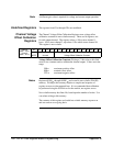
Offset_DAC
Registers
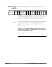
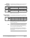
The Offset_DAC Registers are used to program the next offset value on a
channel. There are 16 registers, one for each output channel. The register
at base + 80
16
programs channel 1, base + 82
16
programs channel 2, up to
base +9E
16
to program channel 16. Values loaded in these registers are
applied to the output immediately (no trigger condition is required).
Address
Base + 80
16
through
Base + 9E
16
Bit 15 14 13 12 11 10 09 08 07 06 05 04 03 02 01 00
msb lsb
WRITE Unused Output Value
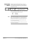
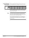
Output Value: Writing a 12-bit value to this field outputs the value on the
channel selected by the base address. Values are in the range:
000
16
maximum positive offset
800
16
nominal (zero) offset
FFF
16
maximum negative offset
Note A different offset value is required for voltage and current output operation.
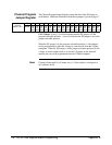
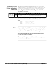
Gain_DAC
Registers
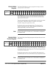
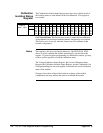
The Gain_DAC Registers are used to program the next gain value on a
channel. There are 16 registers, one for each output channel. The register
at base + A0
16
programs channel 1, base + A2
16
programs channel 2, up to
base BE
16
to program channel 16. Values loaded in these registers are
applied to the output immediately (no trigger condition is required).
Address
Base + A0
16
through
Base + BE
16
Bit 15 14 13 12 11 10 09 08 07 06 05 04 03 02 01 00
msb lsb
WRITE Unused Output Value
Output Value: Writing a 12-bit value to this field outputs the value on the
channel selected by the base address. Values are in the range:
000
16
minimum gain
800
16
nominal gain
FFF
16
maximum gain
Appendix B HP E1418A Register-Based Programming 139